NG-SHM Class D – Servo-Hydraulic Universal Testing Machine

Metal Testing Equipment
Standards




Description
The NG-SHM Class D is a servo-hydraulic universal testing machine for high-force work. The actuator sits above the frame, which leaves one large test space underneath for tension, compression, bending and shear, and gives room for long specimens with high elongation.
Force capacity runs from 600 kN to 2000 kN, and the machine is calibrated to Class 1 or Class 0.5 of ISO 7500-1. That class is the number that matters on a testing machine: it states how far the indicated force may deviate from the true force, and it is what makes a result defensible when a customer or an auditor asks. Class 0.5 halves the permitted error of Class 1.
600 - 2000 kN
Force capacity, three models
Single zone
One space for tension, compression, bending, shear
2 or 4
Columns, depending on model
Class 0.5
Calibration accuracy, ISO 7500-1
Typical work: fasteners, rebar, chain, welds and castings.
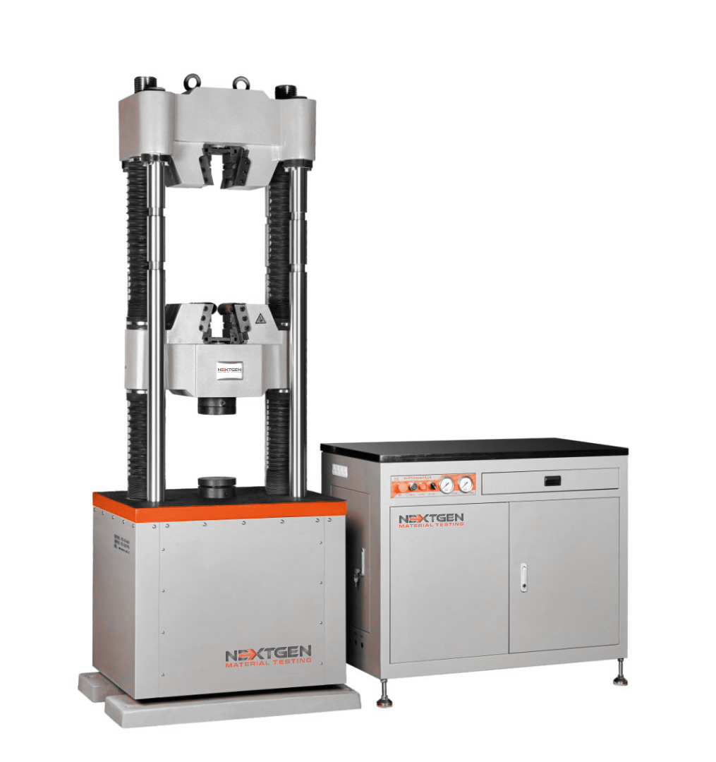
Load frame, hydraulic power unit and control desk.
The actuator sits above the test space.
NG-SHM Class D in operation.
NG-SHM Class D Features
A hydraulic frame is only as good as its alignment and its grips: everything below is aimed at keeping the load axial and the specimen held.
Single zone design
Every test type finishes in one space, which keeps the footprint down and the workflow short.
Upper actuator
Mounted above the frame for axis alignment and shock absorption, and the test space is adjusted from there.
Wedge hydraulic grips
Advanced wedge type hydraulic tensile grips hold high strength material without slipping.
Long travel cylinder
A double-acting cylinder with a long stroke takes different specimen lengths. Piston and rod are forged in one body and sealed with quality components.
Guided cylinder
High-accuracy guidance keeps lateral force off the cylinder, which is what the sealing components live on.
“I” shape transducer
The force transducer holds its linearity and stability across the range.
Encoder feedback
A quality encoder gives the displacement measurement and the control loop their accuracy.
Servo valve
Fast response and accurate control, and it stays simple to handle and maintain.
Drive motor
High starting torque, low noise and low vibration, with high efficiency.
Main Cylinder
The cylinder is the part that decides how long the machine holds its accuracy under repeated high loads:
Plated piston rod
Nickel and chrome plating up to 0.1 mm thick keeps corrosion and wear off the rod.
Extra thick rod
The rod is sized for stiffness, so lateral loading does not bend it.
One-body forging
Piston and rod are forged as one piece and take impact without a joint to fail.
Double sealing
U-shaped sealing components with a double ring hold zero leakage.
Halite guidance ring
The wearing ring resists lateral force at low friction.
Zero clearance connection
The pre-loaded joint between rod and upper grip removes play from the load path.
Copper melting process
The piston and guide sleeve wearing ring is made by a copper melting process, which NextGen rates at five times the life of the usual polymer ring.
Hydraulic Power Unit
The power unit is where the energy, the heat and the noise of a hydraulic machine are decided. This one runs a pressure servo: the pump only delivers what the cylinder is asking for.
Pressure servo regulation
A logic valve holds the system pressure no more than 1 MPa above the cylinder pressure. Low test force means low pump pressure; as the force rises, the pump follows.
Adjustable differential
The differential pressure is adjustable, which keeps the test free of shaking while saving energy and heat.
Low noise
The gear pump keeps noise at or below 70 dB.
Low heating and cooling
The differential servo control keeps heat down, and the semi-open unit carries an air-cooling device that starts automatically at the temperature set on the oil gauge. Total system heating power is 2 kW.
Triple filtration
Particles are down below 5 microns before the oil reaches the servo valve, which is what the valve's service life and control accuracy depend on.
Overload protection
Above the rated pressure the relief valve overflows and protects the system.
Two pressure stages
A 25 MPa high pressure part and a 50 MPa super high pressure part: the main cylinder works at about 25 MPa, the clamping cylinder at about 48 MPa, both driven by a single motor and pump.
Two differential circuits
One returns the piston quickly after a test. The other grips the specimen at low pressure first and only then applies the extra-high pressure, so the sample is not crushed on clamping, and the pressure releases automatically when it breaks.
Service access
The semi-open structure opens at the rear through two doors for maintenance and part replacement.
Measurement and Reporting
Force comes from the transducer and the encoder gives crosshead position, but elongation on a metal specimen is measured on the specimen itself: an extensometer is clipped to the gauge length, which is what ASTM E8 and ISO 6892-1 expect for modulus and yield results. The machine runs GenTest, which records the curve and produces the report against the method you selected.
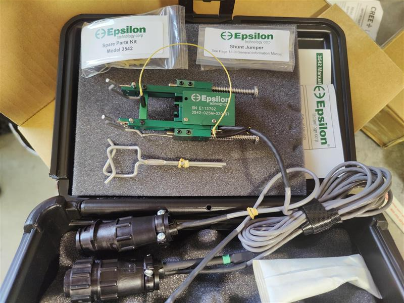
Extensometer for elongation on the gauge length.
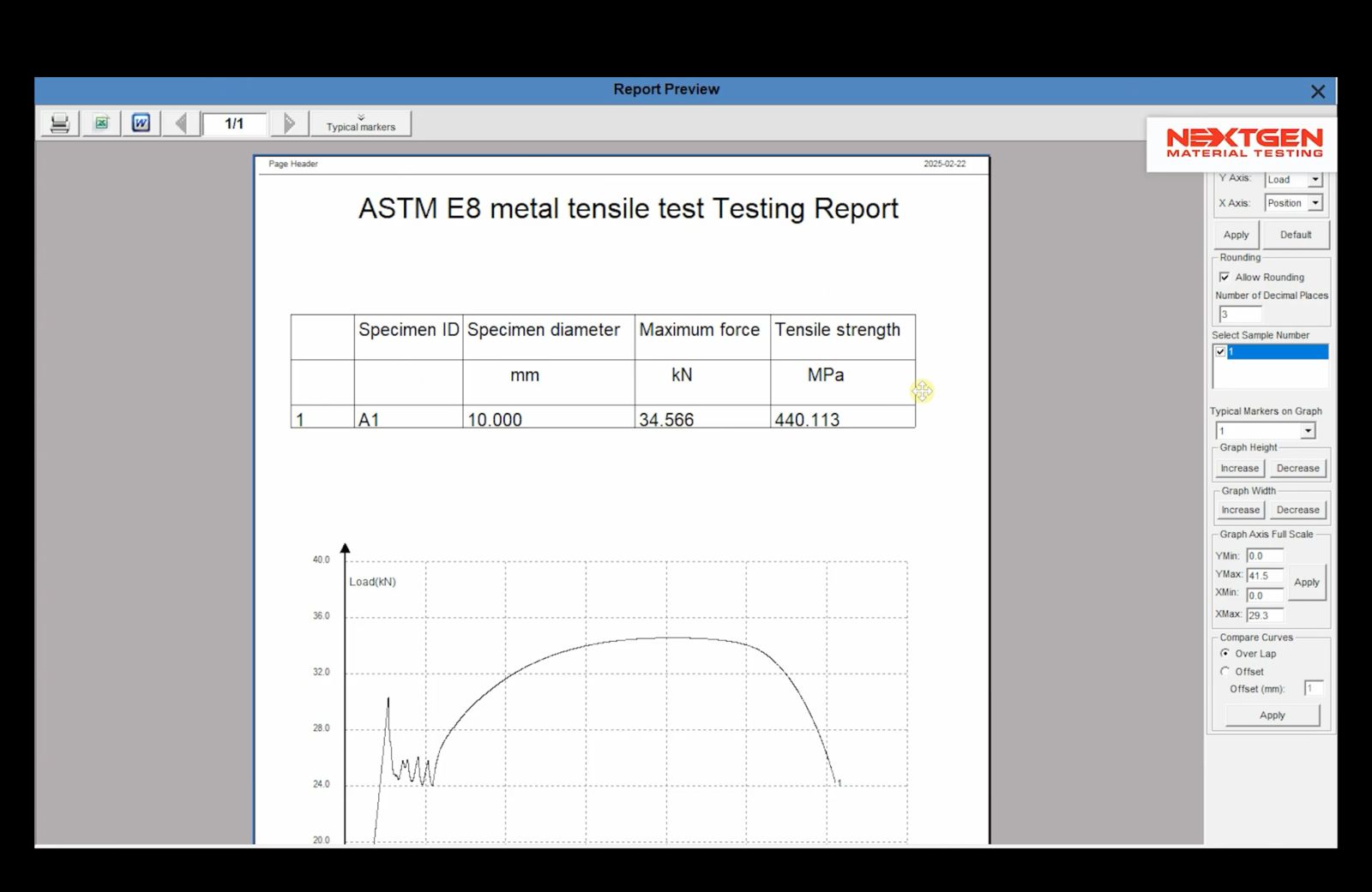
GenTest report: ASTM E8 tensile result and curve.
NG-SHM Class D Technical Specifications
Three models share the frame architecture and differ in capacity, test space and footprint. Check the column spacing and the tension space against your longest specimen, and the power unit dimensions against the floor you have.
| Specification | SHM605 | SHM106 | SHM206 |
|---|---|---|---|
| Class | Class D | ||
| Capacity | 600 kN (134,885.36 lbf) | 1000 kN (224,808.94 lbf) | 2000 kN (449,617.88 lbf) |
| Calibration Accuracy | Class 1 / Class 0.5 | ||
| Force Range | 1% - 100% FS | ||
| Force Accuracy | Better than ±1% / ±0.5% | ||
| Extension Range | 1% - 100% FS | ||
| Extension Accuracy | Better than ±1% / ±0.5% | ||
| Extension Resolution | 1/350,000 of maximum extension | ||
| Force Loading Speed | 0.02% - 2% FS/s | ||
| Actuator Up Speed | 9.1″ (230 mm)/min | 9.1″ (230 mm)/min | 7.9″ (200 mm)/min |
| Actuator Down Speed | 12.2″ (310 mm)/min | 14.2″ (360 mm)/min | 12.2″ (310 mm)/min |
| Actuator Stroke | 22.8″ (58 cm) | 26.8″ (68 cm) | 30.7″ (78 cm) |
| Column Number | 2 | 4 | 4 |
| Column Spacing (test space width) | 18.7″ (47.5 cm) | 22.6 × 14″ (57.5 × 35.5 cm) | 30.3 × 18.5″ (77 × 47 cm) |
| Maximum Tension Space | 23.6″ (60 cm) | 27.6″ (70 cm) | 31.5″ (80 cm) |
| Maximum Compression Space | 16.5″ (42 cm) | 18.1″ (46 cm) | 21.3″ (54 cm) |
| Round Specimen Diameter | Ø10 - Ø40 mm | Ø15 - Ø55 mm | Ø15 - Ø70 mm |
| Flat Specimen Thickness | 2 - 30 mm | 2 - 40 mm | 10 - 70 mm |
| Compression Platens | 5.9″ (150 mm) | 7.9″ (200 mm) | 7.9″ (200 mm) |
| Frame Dimensions (L × W × H) | 29.1 × 15.7 × 111″ (74 × 40 × 282 cm) | 34.3 × 25.6 × 129″ (87 × 65 × 327 cm) | 47.2 × 35.4 × 150″ (120 × 90 × 382 cm) |
| Hydraulic Power Unit (L × W × H) | 19.7 × 34.6 × 36.4″ (50 × 88 × 92.5 cm) | 28 × 44.5 × 43.3″ (71 × 113 × 110 cm) | 47.2 × 35.4 × 43.3″ (120 × 90 × 110 cm) |
| Power Consumption | 5 kW | 8.5 kW | 12 kW |
| Frame Weight | 6,613.86 lbs (3,000 kg) | 13,227.74 lbs (6,000 kg) | 19,841.60 lbs (9,000 kg) |
Note: platen size is specified with the configuration; tell us what you compress and we will confirm which platen ships with your machine.
Send us the specimen you break most often, its size and the standard you test to, and we will confirm which Class D capacity and which grips your laboratory needs.
For Laboratories
Need Additional Quality Control Equipment to Build Your Laboratory?
Servo-hydraulic universal testing is only one part of a complete quality control laboratory. NextGen can help you equip your entire lab with impact testers, notching and broaching systems, cooling chambers, tensile testers, hardness testers, specimen preparation equipment, and other supporting solutions, all coordinated as one complete project.
- One partner to equip your complete laboratory
- Installation, training, calibration
- Support for the life of the equipment
FAQs
The NG-SHM Class D is a servo-hydraulic universal testing machine for high-force work: tension, compression, bending and shear on fasteners, rebar, chain, welds and castings.
Force capacity runs from 600 kN to 2000 kN across three models, and the machine is calibrated to Class 1 or Class 0.5 of ISO 7500-1. The actuator is mounted above the frame, which leaves one large space underneath for every test type and gives room for long specimens with high elongation.
We supply it to laboratories that test components rather than prepared coupons, where the specimen geometry varies and the failure is sudden. The design of the cylinder, the grips and the hydraulic power unit all follow from that requirement.
It sits in the same family as the rest of our servo-hydraulic machines, which differ mainly in how the test space is arranged.
Mounting the actuator above the test space leaves a single large working area underneath, so tension, compression, bending and shear are all performed in the same place without a second zone taking up frame height.
The arrangement also serves axis alignment and shock absorption, and the test space is adjusted from the actuator itself. Alignment is not a detail on a tensile machine: a specimen loaded off axis reports a lower strength and often breaks outside the gauge length, which invalidates the result.
The practical benefit is room for specimens that stretch a long way before they fail, which is exactly what ASTM E8 tension testing on ductile steel produces.
For laboratories with limited ceiling height, the single zone layout also keeps the overall frame shorter than a dual zone machine of the same capacity.
Single zone means every test type finishes in one space: tension, compression, bending and shear all use the same working area under the actuator.
The trade is footprint against setup time. A single zone keeps the machine compact and the workflow short, but fixtures are changed when the test type changes, because there is no second space standing ready with platens already rigged.
For a laboratory that runs long batches of one test type, that is the right trade: the fixture goes in once and stays. For a laboratory that alternates constantly between pulling and crushing, the dual zone Class B suits that pattern better.
We are happy to work through the actual mix of testing with you before the layout is chosen, because it is not a decision that can be changed afterwards.
Three models are offered: SHM605 at 600 kN (134,885 lbf), SHM106 at 1000 kN (224,808 lbf) and SHM206 at 2000 kN (449,617 lbf).
Capacity should be chosen from the strongest specimen you expect, with headroom above it, and with the lower end of the verified range in mind as well. A machine sized for the heaviest test that might ever arrive will push routine work toward the bottom of its range, where the permitted error is largest in relative terms.
Test space, stroke and specimen ranges grow with the capacity, so the model decision usually settles the fixture question at the same time.
Send us the specimen you break most often, its size and the standard you test to with a quotation request and we will confirm the capacity and the grips together.
The machine is calibrated to Class 1 or Class 0.5 of ISO 7500-1.
That class is the number that matters on a testing machine. It states how far the indicated force may deviate from the true force, and it is what makes a result defensible when a customer or an auditor asks. Class 0.5 halves the permitted error of Class 1.
Which class a laboratory needs is normally set by its accreditation and by the specifications it reports against. Where a testing house serves several customers, the stricter class is the safer purchase because it satisfies both.
The equivalent North American verification procedure is ASTM E4, and we can prepare the machine for either.
Force and extension both range from 1% to 100% of full scale, with accuracy better than ±1% or ±0.5% depending on the calibration class. Extension resolution is 1/350,000 of maximum extension.
The 1% lower limit is the figure that catches people out. Below it the reading falls outside the verified range of the machine, so capacity should be matched to the work rather than bought as large as the budget allows.
Resolution and accuracy are different properties. Resolution describes the smallest step the system can show; accuracy describes how close the value is to the truth. Both matter, and a fine resolution on a poorly verified machine proves nothing.
We can supply the machine with verification in place so that it enters service ready to produce reportable results.
Elongation is measured on the specimen itself. An extensometer is clipped to the gauge length, which is what ASTM E8 and ISO 6892-1 expect for modulus and yield results.
Crosshead travel is not a substitute. It includes the take-up of the grips and the elastic stretch of the frame, and on a short specimen that error is large enough to move a yield figure by a margin a customer would notice.
The machine measures crosshead position with an encoder, and that measurement is used for control and for positioning, but the two numbers answer different questions and should not be confused in a report.
Tell us the standards you report to and we will quote a suitable extensometer with the frame.
A quality encoder provides the displacement measurement and gives the control loop its accuracy.
Position feedback is what allows the machine to hold a rate rather than a valve opening. Without it a hydraulic machine can only be driven at a fixed command, and the actual speed then changes as the specimen yields and the load falls away.
It is also what makes displacement control usable as a test mode in its own right, which some component tests and most compression work require.
It is not the same measurement as elongation on the specimen, which is read by an extensometer on the gauge length.
Force loading speed runs from 0.02% to 2% of full scale per second.
Standards limit the rate because the yield strength a metal reports depends on how quickly it is loaded. ISO 6892-1 defines those limits for room temperature tensile testing, and a machine has to sit inside them for the whole elastic region rather than on average.
Holding a slow steady rate is harder for a hydraulic machine than moving quickly, which is why the servo valve, the encoder feedback and the pressure regulation on this machine are specified the way they are.
If your specification names a stress rate, send it over and we will confirm that the model you are considering covers it for your specimen sizes.
Actuator speeds are 230, 230 and 7.9″ (200 mm)/min upward on the SHM605, SHM106 and SHM206, and 310, 360 and 12.2″ (310 mm)/min downward.
These are positioning speeds rather than test speeds. Stroke is 58, 68 and 30.7″ (78 cm) across the three models, so on a long specimen the travel between tests is a real part of the working day and worth considering where throughput matters.
The test rate itself is set by the method in the software and by the force loading speed range, not by the maximum actuator speed.
The two differential circuits in the hydraulic unit include one that returns the piston quickly after a test, which is what keeps that dead time down.
Maximum tension space is 60, 70 and 31.5″ (80 cm) on the three models, and maximum compression space is 42, 46 and 21.3″ (54 cm).
Column spacing is 18.7″ (47.5 cm) on the SHM605, 22.6 × 14″ (57.5 x 35.5 cm) on the SHM106 and 30.3 × 18.5″ (77 x 47 cm) on the SHM206. Those figures set the widest fixture the frame will accept, which is often the real limit rather than the specimen itself.
Check the tension space against your longest specimen including the grips, not the specimen alone. Wedge grips and an extensometer take up room that is easy to forget at the specification stage.
Our team will check the numbers against your actual test pieces as part of the quotation.
Two columns on the SHM605, four on the SHM106 and the SHM206.
Columns guide the moving parts and carry the reaction. More of them on the larger frames is what keeps the load path straight when the force more than triples, and alignment is what a tensile result depends on: a specimen loaded off axis reports a low strength and often breaks outside the gauge length.
The column arrangement also sets the width of the working space, so it decides which fixtures fit as well as how the frame behaves under load.
Both figures, spacing and count, are quoted per model so the frame can be matched to the fixtures a laboratory already owns.
Round specimens are covered from Ø10 to Ø40 mm on the SHM605, Ø15 to Ø55 mm on the SHM106 and Ø15 to Ø70 mm on the SHM206.
Flat specimens run 2 to 30 mm thick, 2 to 40 mm and 10 to 70 mm across the same three models. Anything outside those ranges is a grip question before it is a frame question, because it is the jaws that have to hold the section without slipping or crushing it.
Where a laboratory tests a wide spread of sizes, more than one set of jaws is normal and is cheaper than compromising at either end of the range.
Send the section and the standard with a request for pricing and we will confirm which jaws are needed.
The machine uses advanced wedge type hydraulic tensile grips, which hold high strength material without slipping.
A wedge grip tightens as the load rises, so the clamping force follows the test instead of being set once by hand at the start. On high strength steel that is the difference between a break in the gauge length and a specimen that pulls out of the jaws with no usable result.
Where the break happens is not a detail: ISO 6892-1 expects failure inside the gauge length for the result to count, and a grip failure wastes the specimen and the preparation behind it.
Grips are quoted with the frame because the correct jaw depends on the specimen rather than on the machine.
The hydraulic unit runs two differential circuits. One of them grips the specimen at low pressure first and only then applies the extra-high pressure.
That sequence matters on components with thin walls, on tube, and on any specimen where full clamping force applied instantly would deform the section before the test begins. A deformed grip area changes the result and can move the failure to the jaw.
The same circuit releases the pressure automatically when the specimen breaks, so the grips are not left loaded after a failure and the broken halves can be removed safely.
Together the two behaviours allow the same machine to hold a hardened bolt and a thin walled section without a change of technique.
The system is built with a 25 MPa high pressure part and a 50 MPa super high pressure part. The main cylinder works at about 25 MPa and the clamping cylinder at about 48 MPa, both driven by a single motor and pump.
Separating them means the clamping force does not have to come from the same pressure that drives the test. Clamping needs high pressure over a small area; the test needs controlled pressure over a large one, and forcing both from a single stage compromises one of them.
Using one motor and pump for both keeps the power unit compact and the maintenance simple, which matters in a laboratory rather than a plant room.
It is one of the reasons the machine holds grip force steady through a long test without a separate clamping unit standing beside it.
The unit runs a pressure servo: a logic valve holds system pressure no more than 1 MPa above cylinder pressure, so the pump delivers what the cylinder is asking for instead of running at full pressure all day.
The differential pressure is adjustable, which keeps the test free of shaking while saving energy and heat at the same time. Oil that is not pressurised unnecessarily does not have to be cooled afterwards.
The gear pump keeps noise at or below 70 dB, total system heating power is 2 kW, and the semi-open unit carries an air-cooling device that starts automatically at the temperature set on the oil gauge.
For a laboratory the practical result is a machine that can stand in the same room as the people using it rather than behind a wall.
Triple filtration brings particles down below 5 microns before the oil reaches the servo valve.
Contamination is the usual cause of servo valve trouble, and the valve is what the control accuracy and the service life of the whole system depend on. A valve damaged by dirty oil does not fail cleanly: it degrades, and the symptoms look like control problems long before anyone suspects the oil.
Filtration is therefore maintenance that pays for itself rather than a specification line. Oil condition and filter changes belong in the laboratory routine alongside verification.
We can advise on the service interval that suits your duty cycle when the machine is commissioned.
Above the rated pressure the relief valve overflows and protects the system.
It is the hydraulic equivalent of a fuse: the excess energy goes somewhere harmless rather than into the frame, the fixture or the specimen. On a 2000 kN machine that matters to the operator as much as to the equipment.
Overload protection is one part of a wider picture that also includes the guided cylinder, the pre-loaded connection in the load path and the automatic pressure release when a specimen breaks.
As with any high-force equipment, we recommend that these functions are covered in operator training at installation rather than read about later.
The piston and rod are forged as one body, so there is no joint to fail under impact, and the rod is plated with nickel and chrome up to 0.1 mm thick against corrosion and wear.
The rod is sized for stiffness so that lateral loading does not bend it, and a halite guidance ring resists lateral force at low friction. Sealing is by U-shaped components with a double ring, held to zero leakage.
These are the parts that decide how long a hydraulic machine holds its accuracy under repeated high loads. A cylinder that develops play or leakage does not stop working; it quietly changes what the machine measures.
The same cylinder design is used on the Class DP frames.
The piston and guide sleeve wearing ring is produced by a copper melting process, which NextGen rates at five times the life of the usual polymer ring.
It is a maintenance figure rather than a performance one. The wearing ring is a consumable on any hydraulic cylinder, and how often it has to be changed decides how much downtime the machine costs over its working life.
For a laboratory running production release testing, downtime is the expensive part rather than the parts themselves, because specimens and schedules do not wait for a cylinder rebuild.
Service intervals depend on duty cycle, and our team can advise on what to expect for your pattern of use.
The joint between the piston rod and the upper grip is pre-loaded to zero clearance.
Any free play in that connection would appear at the start of the curve as false compliance, and on a stiff specimen it would move the modulus. It would also produce a small shock every time the load reverses, which is the last thing wanted in a machine measuring to half a percent.
Removing it is why the connection is pre-loaded rather than simply bolted together, and it is one of the details that separates a machine built for measurement from one built only to apply force.
The guided cylinder and the one-body forged piston serve the same purpose from the other end of the load path.
The machine runs our GenTest software, which records the curve and produces the report against the method you selected.
Method-driven testing is what keeps a result reproducible across operators. The control steps, the calculations and the report template are all part of the method rather than of the operator's habits, so two people on two shifts produce results that can be compared.
It also matters when a result is questioned months later: the method, the raw curve and the report are one record rather than three files that have to be matched up by date.
The same software runs the rest of our universal testing machines, so a laboratory with several frames keeps one set of methods.
Power consumption is 5 kW, 8.5 kW and 12 kW across the three models. Frames measure 29.1 × 15.7 × 111″ (74 x 40 x 282 cm), 34.3 × 25.6 × 129″ (87 x 65 x 327 cm) and 47.2 × 35.4 × 150″ (120 x 90 x 382 cm).
The hydraulic power units are 19.7 × 34.6 × 36.4″ (50 x 88 x 92.5 cm), 28 × 44.5 × 43.3″ (71 x 113 x 110 cm) and 47.2 × 35.4 × 43.3″ (120 x 90 x 110 cm) and stand separately from the frame, so the floor plan has to allow for both plus the hose run between them.
Frame weights are 6,613 lbs (3,000 kg), 13,227 lbs (6,000 kg) and 19,841 lbs (9,000 kg). Floor loading and ceiling height therefore come first in the layout, followed by the route into the building for installation.
We will go through the site requirements with you as part of the quotation rather than after the order is placed.
The semi-open structure of the hydraulic power unit opens at the rear through two doors for maintenance and part replacement.
Plan the installation with that access kept clear. Oil, filters and seals are the recurring items on any hydraulic machine, and a power unit pushed into a corner turns a routine service into a lifting operation.
Access matters for the frame as well, particularly around the grips, where jaw changes and cleaning are part of normal operation rather than occasional maintenance.
Where a laboratory runs a preventive maintenance programme, we can set out what the machine needs and at what interval so it can be scheduled alongside verification.
Compression platens are 5.9″ (150 mm) on the SHM605 and 7.9″ (200 mm) on the SHM106 and SHM206.
Platen size limits the compression side of the working space. A block or a casting wider than the platen cannot be loaded squarely, and an off-centre compression test loads the columns and the cylinder as well as the specimen.
Which platen ships with a machine depends on the model and on the compression work it is bought for, so it is specified with the rest of the configuration rather than fixed in advance. Laboratories testing concrete cubes, castings or large blocks usually take the largest platen the frame allows.
Tell us what you compress and we will confirm the platens with the offer.
Related Products
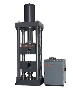
NG-SHM Class DP – Servo-Hydraulic Universal Testing Machine
NG-SHM Class DP is a high-force servo-hydraulic testing machine with an upper actuator, single-zone test space, and side-action hydraulic wedge grips. Available in 600 kN, 1000 kN, and 2000 kN capacities, it supports tension, compression, bending, and shearing tests on metals and structural specimens. Its automatic clamping adjustment, dual-direction grip alignment, precision transducer, and long-travel cylinder help deliver stable, repeatable results.
Read more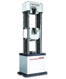
NG-SHM Class C – Servo-Hydraulic Universal Testing Machine
NG-SHM Class C is a servo-hydraulic universal testing machine for high-force metal testing, with capacity options of 600 kN and 1000 kN. Its longer jaw face is designed for tensile testing of stranded steel wire, while the 6-column frame, dual-zone test space, hydraulic wedge grips, quick-return valve, and precision load cell support accurate, repeatable testing of rebar, fasteners, chains, welds, and castings.
Read more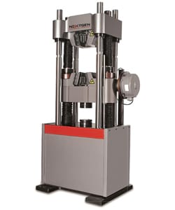
NG-SHM Class B – Servo-Hydraulic Universal Testing Machine
NG-SHM Class B is a high-force servo-hydraulic universal testing machine for tensile, compression, and flexural testing of metals and other high-strength materials. Available from 300 kN to 3000 kN, it uses a rigid multi-column frame, dual-zone test space, hydraulic wedge grips, and precise load-cell measurement to support reliable testing of fasteners, rebar, chains, welds, castings, and structural components.
Read more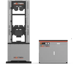
NG-SHM Series A – Servo-Hydraulic Universal Testing Machine (300–3000 kN)
NG-SHM Series A is a high-force servo-hydraulic universal testing machine for static mechanical testing of metals and structural components. Available from 300 kN to 3000 kN, it uses a high-stiffness multi-column frame and dual-zone layout for tensile and compression work. Hydraulic wedge grips, extensometer compatibility, and GenTest software support testing of rebar, fasteners, chains, welds, castings, and large metallic specimens.
Read more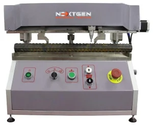
GenMark 500 – Automatic Gauge Length Marking Machine
The GenMark 500 is a full-automatic gauge length marking machine for metal bar, rebar and wire rod, applying the reference marks used to determine elongation after fracture. A servo-driven lead screw sets 5 mm or 10 mm spacing and a pneumatic tungsten steel needle marks specimens up to 500 mm gauge length, supporting ISO 6892-1 and ASTM E8/E8M workflows. Adjustable marking force, quick needle changes, and fixtures for both round and flat samples keep specimen preparation consistent across operators and shifts.
Read more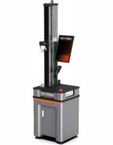
NG-EML Series A – Single-Column Universal Testing Machine (50 N – 5 kN)
NG-EML Series A is a compact single-column benchtop universal testing machine for low-force tensile, compression, and flexural testing. Covering 50 N to 5 kN capacity options, it is suited for rubber, plastics, adhesives, films, foams, wires, metals, composites, and consumer products. Its electromechanical frame, high-speed servo actuation, GenTest software, and standards support make it practical for R&D and routine QC.
Read more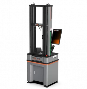
NG-EML Series B – Dual-Column Universal Testing Machine (100 N – 10 kN)
NG-EML Series B is a dual-column benchtop electromechanical universal testing machine for precision testing from 100 N to 10 kN. Built for research and industrial labs, it supports tension, compression, flexural, and component testing of composites, high-strength metals, polymers, films, foams, and rubber. Its compact rigid frame, advanced control accuracy, and GenTest software help deliver repeatable results in limited lab space.
Read more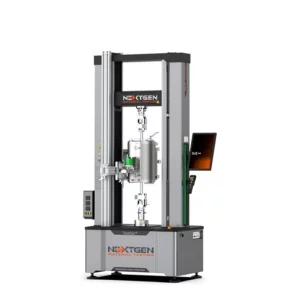
NG-EML Series C – Dual-Column Universal Testing Machine (5–50 kN)
NG-EML Series C is a dual-column electromechanical universal testing machine available in bench-top and floor-standing formats from 5 kN to 50 kN. Built for tension, compression, flexural, shear, and peel testing, it combines Class 0.5 accuracy, a servo direct-drive system, high-rigidity frame, touchscreen control, and GenTest software to support precise testing of metals, composites, rubber, plastics, and polymers.
Read more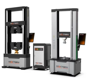
NG-EML Series D – Floor-Standing Universal Testing Machine (50–1000 kN)
NG-EML Series D is a heavy-duty floor-standing electromechanical universal testing machine for high-capacity tensile, compression, and flexural testing. Available from 50 kN to 1000 kN, it is built for high-strength steels, advanced composites, alloys, and challenging research materials. Its rigid dual-column frame, servo direct-drive system, closed-loop control, safety protections, and GenTest software support stable, accurate testing.
Read more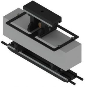
Flexure Fixtures for Large and Brittle Specimens
These flexure fixtures are designed for precise bending tests on large, brittle, or high-strength specimens, including metals, ceramics, composites, concrete, and construction materials. Compatible with hydraulic universal testing machines, they support single-point, three-point, and four-point bending configurations with adjustable spans and roller supports. Capacities up to 2000 kN help laboratories evaluate flexural strength, deformation behavior, and structural integrity.
Read more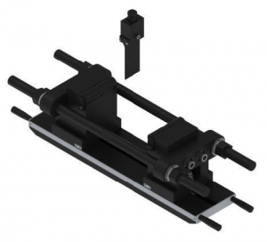
Heavy-Duty Bending Fixtures for Hydraulic Flexural Testing
Heavy-duty bending fixtures support high-force flexural testing of metals, composites, ceramics, reinforcing bars, and structural materials on hydraulic universal testing machines. Designed for loads up to 2000 kN, they use secure fixing blocks, positioning-pin connections, adjustable mandrel options, and wide test spaces to maintain stability. GB/T 232, GB1499.1, and GB1499.2 compliance helps laboratories perform accurate, repeatable bend evaluations.
Read more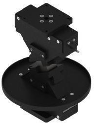
Splitting Fixtures for Rock and Concrete Testing
Splitting fixtures for indirect tensile testing are designed for rock, concrete, and composite specimens tested on hydraulic universal testing machines. Built for demanding geotechnical, mining, and structural-materials laboratories, they provide stable specimen support, rugged construction, and secure mounting under high loads. Compatibility with cylindrical and cubic samples, GB/T 23561.11 alignment, and capacities up to 2000 kN support repeatable shear and splitting evaluations.
Read more