NG-SHM Series A – Servo-Hydraulic Universal Testing Machine (300–3000 kN)

Metal Testing Equipment
Standards
- ASTM A370
- ASTM D3039
- ASTM E4
- ASTM E8
- ASTM E21
- ASTM E92
- ASTM F606
- EN 10002-1
- EN ISO 15630-1
- ISO 527
- ISO 6892-1
- ISO 6892-2
- ISO 7500-1
- ISO 9513




Description
The NG-SHM Series A applies large static forces under control, for laboratories characterising material strength. Capacities run from 300 kN to 3000 kN, which covers the oversized metallic specimens an electromechanical frame cannot reach. A high-stiffness multi-column frame keeps deflection out of the load path, and that deflection is exactly what corrupts a yield or elongation reading on a soft frame.
The dual-zone layout is what changes the working day: tension is pulled in the upper zone while compression fixtures stay mounted on the lower platen, so a laboratory alternating tensile and compression work stops reconfiguring the machine between tests. It suits yield strength determination, proof testing, elongation analysis, fracture observation, modulus evaluation, QC acceptance and research work, with extensometers and hydraulic wedge grips for smooth, ribbed, round or flat samples.
300 - 3000 kN
Five capacities
Dual zone
Tension above, compression below
4 or 6
Columns, by model
Class 0.5
Calibration accuracy, ISO 7500-1
1200 Hz
DTC-500 control rate
The frame is a 4 or 6 column hydraulic structure with servo-controlled actuation for test space adjustment.
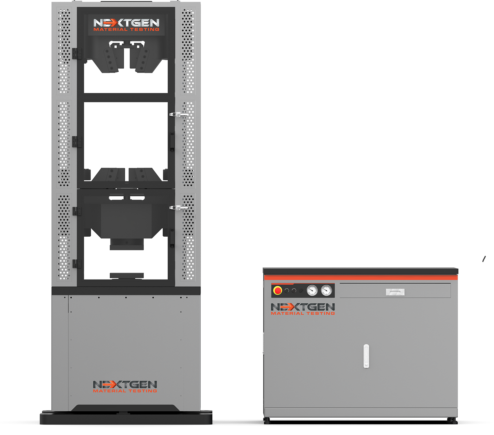
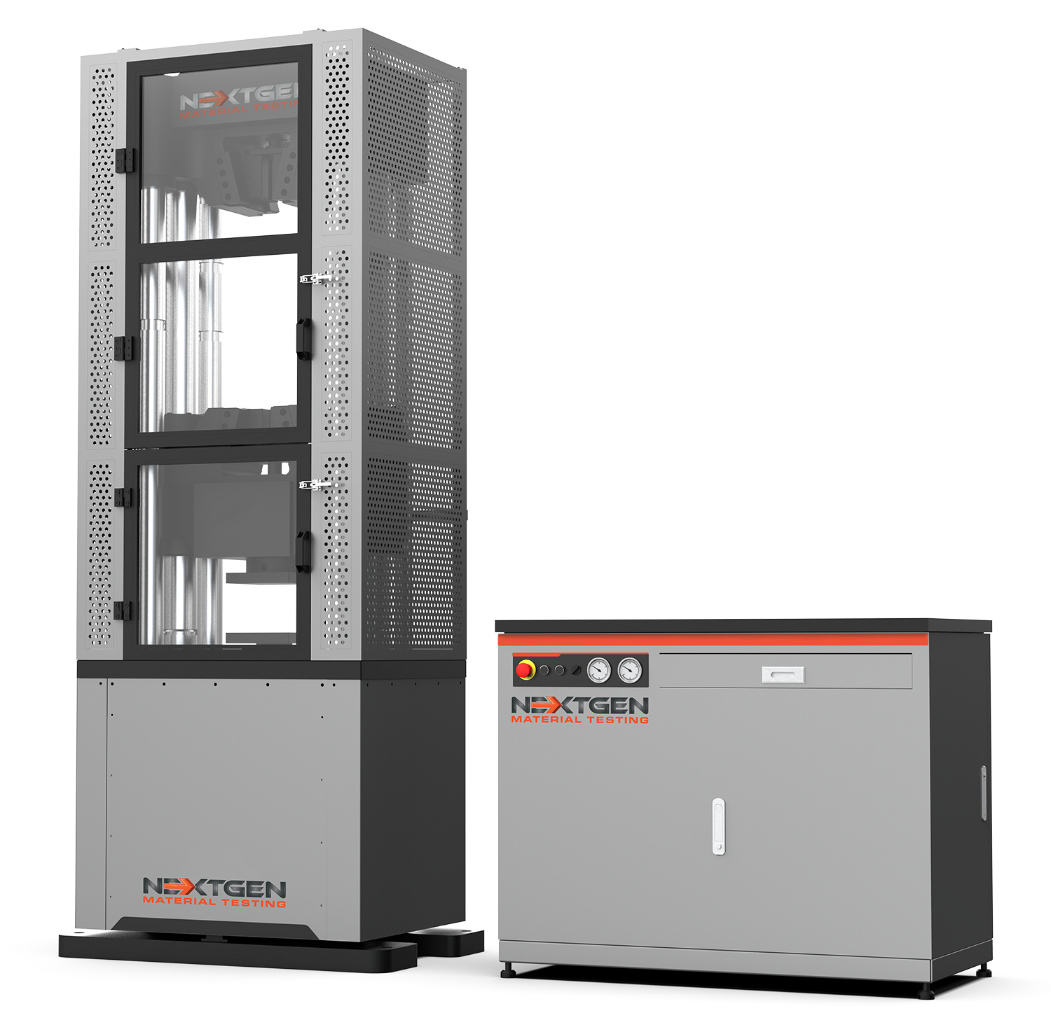
Dual-zone frame with the hydraulic power unit alongside.
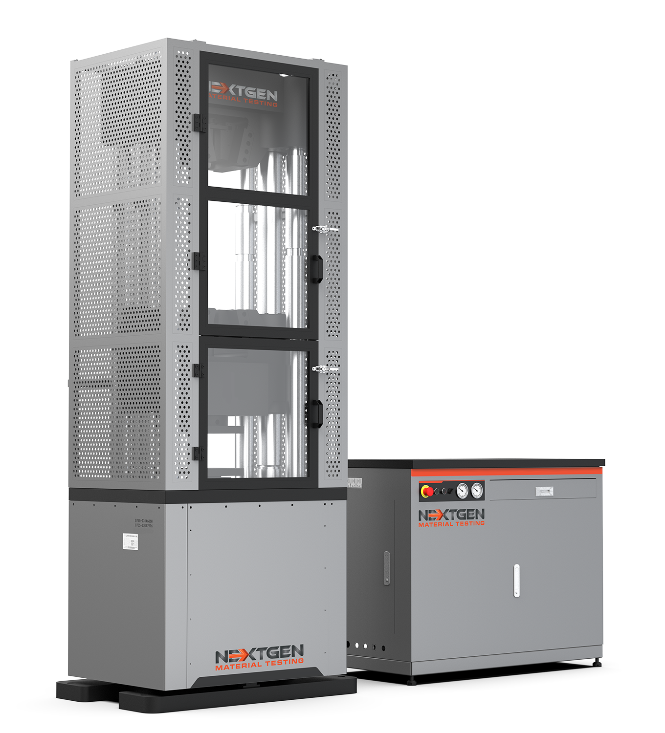
Guarded frame, tension zone above the compression platen.
NG-SHM Series A in operation.
Typical Test Specimens
The Series A takes medium to large metallic samples, structural components and assemblies. What it is normally asked to break:
- Reinforcing steel rebar, threaded bar, smooth bar, structural rod
- Metal plates, billets, heavy gauge sheet and machined test coupons
- Steel wires, cables, chains, anchoring hardware and lifting connectors
- Welded joints, heat-affected zones and welded plate specimens
- Cast and forged components, brackets, automotive and industrial housings
- Bolts, nuts, fasteners, studs, anchor bolts and mechanical couplings
- Pipe segments, round bar, tubes, hollow cylinders and cross-section samples
- Large compression blocks, load-bearing plates and die-forged elements
- High-strength alloys, carbon steel, stainless steel, tool steels and iron-base materials
- Industrial structural components, fittings, joint parts, rail sections and supports
- Tensile and compressive samples to ISO 6892-1 and ASTM E8 / E8M
- Compression specimens to ASTM E9 and related procedures
- Rebar and construction steel to EN ISO 15630-1 and comparable standards
- General metallic components across R&D, QA and batch-release work
NG-SHM Series A Features
The list below is the short version of what the following sections describe in detail:
Multi-stiffness frame
A high-stiffness multi-column load frame that holds alignment and keeps deflection down under high force.
Servo-hydraulic actuation
Stable loading through tension and compression on metallic specimens.
Dual test zone
Tension in the upper section, compression in the lower, with no fixture removal between them.
Hydraulic wedge grips
Secure clamping of round and flat samples at high load.
High-resolution force
A strain-gauge load cell reading 1/500,000 of full scale in tension and compression.
Intelligent power unit
Pressure-regulated hydraulics with a low-noise screw pump and 5 µm filtration.
Active cooling
The HPU cabinet is air-cooled automatically for continuous operation.
Protection logic
Overload, travel limit, temperature monitoring and emergency stop.
DTC-500 controller
24-bit acquisition at a 1200 Hz control rate, with closed-loop force, displacement and extension control.
Connectivity
Ethernet and USB with TEDS support and a noise-resistant signal architecture.
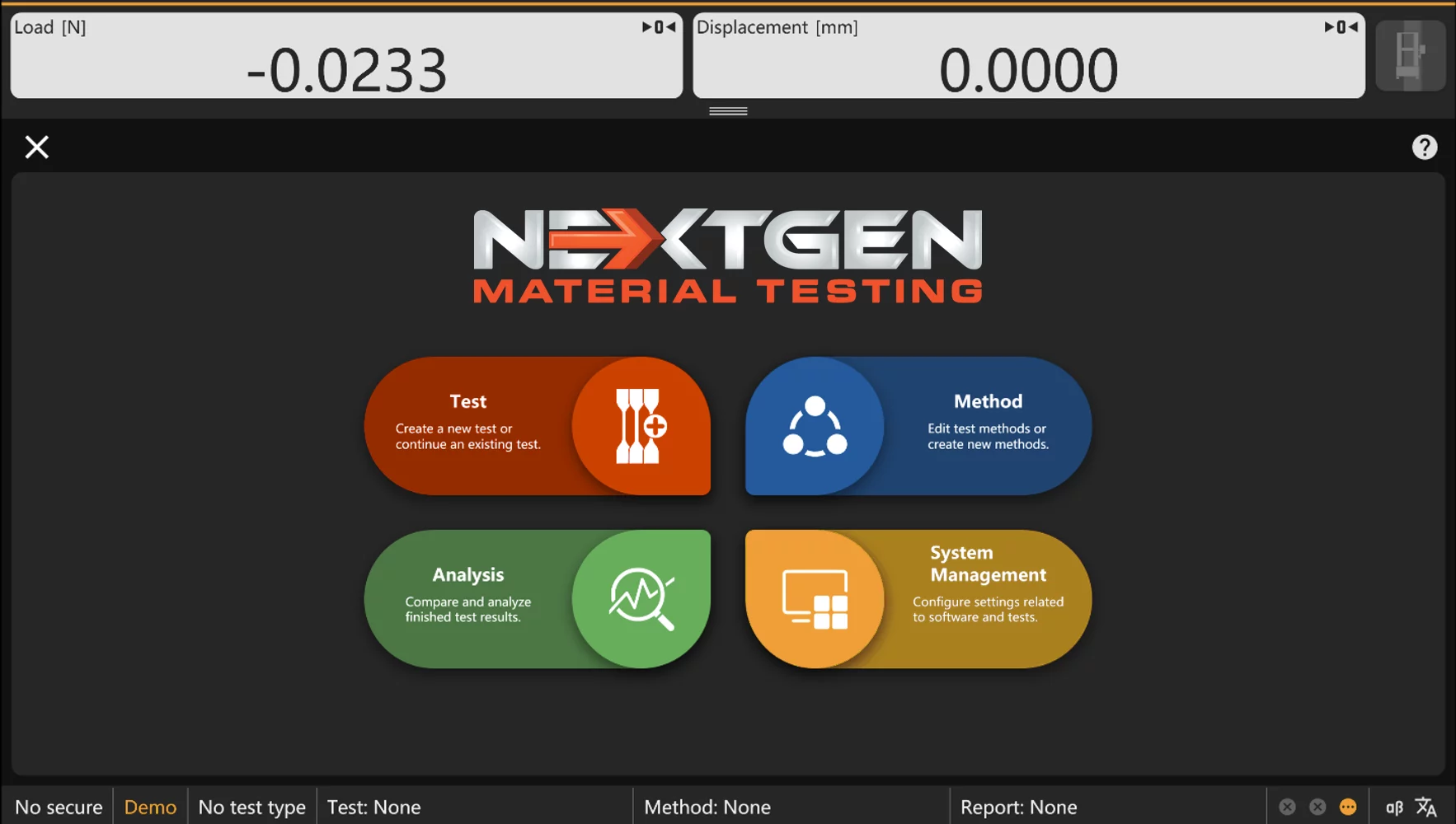
GenTest™ software
Method templates, real-time graphing, automatic results and export.
Frame, Crosshead and Load Cell
Two things decide whether a high-force frame measures what it claims: how little it flexes, and where the force is read.
Lead-screw crosshead
The crosshead is positioned by a lead-screw drive, so the test space is set accurately for the specimen in hand.
4 or 6 column frame
The column count follows the capacity, and the frame is sized for alignment stability rather than minimum weight.
Reinforced beams
Beam reinforcement keeps deflection out of the measurement.
Load cell at the grip
The strain-gauge cell sits at the lower grip and reads force through the specimen, not through the frame.
1/500,000 resolution
Tensile and compressive load are read at 1/500,000 of full scale.
No range switching
The cell works across the full scale without range changes or step divisions, so a single calibration covers the whole test.
Hydraulic Power Unit and Servo Control
The power unit follows demand instead of running at full pressure: it holds an adjustable differential as the load rises and drops the pump output when the force requirement falls. Less energy circulating means less heat, and less heat is what keeps the oil, and with it the control accuracy, stable through a long test sequence. A cartridge valve architecture carries the pressure transitions without a step at either end of the range.
On the control side a low-hysteresis servo valve responds quickly when the force changes, and the rotor-driven screw pump delivers pulse-free flow up to 27.5 MPa, which is what removes flow fluctuation from the reading. Spool-position feedback is standardised, so the valve state can be monitored and maintenance planned instead of discovered.
Pressure-following logic
Output adjusts dynamically to the cylinder demand, cutting thermal and energy load.
Pulse-free delivery
Up to 27.5 MPa from the screw pump, for a stable control response.
Servo-valve regulation
Low hysteresis with diagnostic feedback on spool position.
Automatic cooling
Fan cooling starts at the oil temperature threshold set on the gauge.
5 µm absolute filtration
Multi-stage high-pressure elements protect the servo valve and the pump internals.
Overpressure protection
A relief valve opens above the rated pressure.
Serviceable enclosure
The semi-open cabinet gives direct access, and the backplate comes off without dismantling the cabinet.
Sealed high-pressure lines
Cone-seal bite-type fittings hold their seal through repeated assembly.
DTC-500 Digital Controller
The controller is the part that decides whether a test transitions cleanly from force control to displacement control mid-run, which is what a ramp-hold-cycle procedure needs. The DTC-500 runs three fully digital closed loops and switches between them without instability at the switching point.
Acquisition
6-channel 24-bit A/D, with sampling and control rates up to 1200 Hz.
Digital inputs
Three high-speed channels for encoder or grating ruler feedback up to 4 MHz, at 20-bit input resolution.
Closed loops
Force, displacement and extension, with smooth transitions between modes.
Connectivity
USB and high-speed Ethernet through a dedicated TCP/IP processing chip.
Analog output
Optional dual channels for external force, displacement or extensometer signals.
Transducer recognition
TEDS support identifies the load cell and accessories automatically.
Safety layers
Limit protection, overload protection and emergency stop.
Electronics
A 4-layer PCB for noise immunity, with locking connectors for quick replacement.
GenTest™ Test Software
The machine ships with GenTest™, which holds the method library and turns the run into a report. It covers ASTM, ISO, DIN, EN and BS procedures for tensile, compression, flexural and custom protocols:
- A library of standards-compliant methods for routine and research work
- Modular architecture, expandable with further material or standard packages
- Report templates with export to Excel or Word
- Real-time curves: displacement-load, stress-strain, displacement-time, load-time
- Automatic statistics for Fm, ReL, ReH, Rp and related values
- Unit selection in N, kN, kgf, lbf, MPa, and user-defined units through custom formulas
NG-SHM Series A Technical Specifications
Five models share the architecture and differ in capacity, test space and footprint. Check the column spacing and the tension space against your longest specimen, and the HPU dimensions against the floor plan. The table scrolls sideways on a narrow screen.
| Specification | SHM305 | SHM605 | SHM106 | SHM206 | SHM306 |
|---|---|---|---|---|---|
| Frame Type | Type A | ||||
| Capacity | 300 kN | 600 kN | 1000 kN | 2000 kN | 3000 kN |
| Calibration Accuracy | Class 0.5 | ||||
| Force Accuracy | ±0.5% | ||||
| Force Range | 1% to 100% FS | ||||
| Force Resolution | 1/500000 FS | ||||
| Extension Accuracy | ±0.5% | ||||
| Extension Resolution | 1/500000 of max extension | ||||
| Position Resolution | 0.004 mm | ||||
| Position Accuracy | ±0.5% of reading | ||||
| Actuator Stroke | 5.91 in (150 mm) | 9.84 in (250 mm) | 9.84 in (250 mm) | 9.84 in (250 mm) | 11.81 in (300 mm) |
| Actuator Speed | 0-180 mm/min | 0-140 mm/min | 0-90 mm/min | 0-70 mm/min | 0-100 mm/min |
| Crosshead Speed (adjustment) | 13.78 in/min (350 mm/min) | 10.63 in/min (270 mm/min) | 12.20 in/min (310 mm/min) | 14.17 in/min (360 mm/min) | 9.45 in/min (240 mm/min) |
| Force Loading Speed | 0.05%-2% FS/s | ||||
| Column Number | 4 | 6 | 6 | 6 | 6 |
| Column Spacing (test width) | 16.14 in (410 mm) | 17.13 in (435 mm) | 17.72 in (450 mm) | 28.74 in (730 mm) | 20.87 in (530 mm) |
| Max Tension Space | 20.47 in (520 mm) | 27.95 in (710 mm) | 29.53 in (750 mm) | 35.43 in (900 mm) | 47.24 in (1200 mm) |
| Max Compression Space | 20.47 in (520 mm) | 27.56 in (700 mm) | 29.53 in (750 mm)* | 29.53 in (750 mm) | 39.37 in (1000 mm) |
| Round Specimen Ø Range | Ø10-Ø20 mm / Ø20-Ø32 mm | Ø10-Ø21 mm / Ø21-Ø31 mm | Ø12-Ø23 mm / Ø23-Ø35 mm | Ø15-Ø30 mm / Ø30-Ø55 mm | Ø30-Ø70 mm / Ø70-Ø110 mm |
| Flat Specimen Thickness | 2-13 mm / 13-25 mm | 2-16 mm / 16-30 mm | 2-20 mm / 20-40 mm | 10-40 mm / 40-70 mm | 10-60 mm / 60-100 mm |
| Compression Platens Ø | Ø4.7″ (120 mm) | Ø5.9″ (150 mm) | Ø7.9″ (200 mm) | Ø9.4″ (240 mm) | Ø11″ (280 mm) |
| Frame Dimensions (L×W×H) | 32.28 × 22.44 × 76.97 in (32.3 × 22.4 × 77″ (820 × 570 × 1955 mm)) |
37.01 × 25.59 × 94.49 in (37 × 25.6 × 94.5″ (940 × 650 × 2400 mm)) |
40.16 × 26.38 × 102.36 in (40.2 × 26.4 × 102″ (1020 × 670 × 2600 mm)) |
53.94 × 32.28 × 124.02 in (53.9 × 32.3 × 124″ (1370 × 820 × 3150 mm)) |
52.01 × 37.40 × 155.51 in (52 × 37.4 × 156″ (1320 × 950 × 3958 mm)) |
| HPU Dimensions (L×W×H) | 45.28 × 23.62 × 35.43 in (1150 × 600 × 900 mm) | larger models: 45.28 × 24.80 × 39.37 in (1150 × 630 × 1000 mm) | ||||
| HPU Weight | 661 lb (300 kg) | larger models: 882 lb (400 kg) | ||||
| HPU Flow Rate | 1.32 gal (5 L)/min | 1.32 gal (5 L)/min | 1.32 gal (5 L)/min | 1.9 gal (7.2 L)/min | 3.17 gal (12 L)/min |
| Power Consumption | 2.5 kW | 3.5 kW | 4 kW | 6 kW | 6 kW |
| Power Supply | 220 V AC, 50/60 Hz | ||||
| Frame Weight | 3307 lb (1500 kg) | 5512 lb (2500 kg) | 7716 lb (3500 kg) | 14991 lb (6800 kg) | 22513 lb (10220 kg) |
Frame Dimensions
The letters in the table match the dimension drawing: D is the tensile space, E the compression space and F the test width.
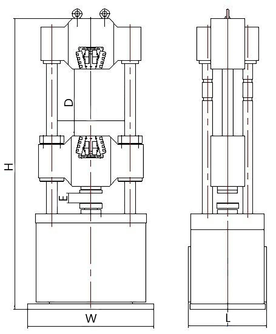
Frame dimension drawing: D tensile space, E compression space, F test width, H overall height.
Model by model, the same dimensions in figures:
| Model | Outside dimensions (L × W × H) | Tensile space (D) | Compression space (E) | Test width (F) | Piston travel |
|---|---|---|---|---|---|
| SHM305 | 32.28 × 22.44 × 76.97 in (32.3 × 22.4 × 77″ (820 × 570 × 1955 mm)) |
20.47 in (520 mm) | 20.47 in (520 mm) | 16.14 in (410 mm) | 5.91 in (150 mm) |
| SHM605 | 37.01 × 25.59 × 94.49 in (37 × 25.6 × 94.5″ (940 × 650 × 2400 mm)) |
27.95 in (710 mm) | 27.56 in (700 mm) | 17.13 in (435 mm) | 9.84 in (250 mm) |
| SHM106 | 40.16 × 26.38 × 102.36 in (40.2 × 26.4 × 102″ (1020 × 670 × 2600 mm)) |
29.53 in (750 mm) | 25.98 in (660 mm)* | 17.72 in (450 mm) | 9.84 in (250 mm) |
| SHM206 | 53.94 × 32.28 × 124.02 in (53.9 × 32.3 × 124″ (1370 × 820 × 3150 mm)) |
35.43 in (900 mm) | 29.53 in (750 mm) | 28.74 in (730 mm) | 9.84 in (250 mm) |
| SHM306 | 52.01 × 37.40 × 155.51 in (52 × 37.4 × 156″ (1320 × 950 × 3958 mm)) |
47.24 in (1200 mm) | 39.37 in (1000 mm) | 20.87 in (530 mm) | 11.81 in (300 mm) |
Note: the compression space for the SHM106 is given as 29.53 in (750 mm) in the specification table and as 25.98 in (660 mm) in the frame dimension table. Both values are marked * above; confirm the figure at the time of order.
Send us the specimen, its size and the standard you test to, and we will confirm which capacity, which grips and which extensometer your work needs.
For Laboratories
Need Additional Quality Control Equipment to Build Your Laboratory?
Servo-hydraulic universal testing is only one part of a complete quality control laboratory. NextGen can help you equip your entire lab with impact testers, notching and broaching systems, cooling chambers, tensile testers, hardness testers, specimen preparation equipment, and other supporting solutions, all coordinated as one complete project.
- One partner to equip your complete laboratory
- Installation, training, calibration
- Support for the life of the equipment
FAQs
For high-force tensile testing of metallic specimens on this universal testing machine, the recommended approach is to use high-load wedge-style gripping, most commonly hydraulic wedge grips, sized to match your specimen geometry and expected peak load. This style of grip is well-suited for securely clamping smooth or ribbed, round or flat metal samples while maintaining alignment during yield and fracture.
Grip selection is typically driven by a few practical factors:
- Specimen type and surface condition, for example smooth round bars versus ribbed rebar, and whether serrated or specialty jaw faces are needed.
- Specimen size range, including diameter for round specimens and thickness for flat specimens, so the correct jaw set and grip body are selected.
- Target force level and test method, so the grip capacity and clamping style match the frame capacity and the way the load is applied.
- Test workflow, including how often you change specimen sizes and whether faster, repeatable hydraulic clamping is preferred.
If you want to confirm the right high-load wedge or hydraulic grip configuration for your metallic specimens and method, review the system details and then learn more or request a quote.
This system meets ISO 7500-1 Accuracy Class 0.5 for force measurement, and it provides a force resolution of 1/500,000 of full scale using a strain-gauge load cell for both tension and compression.
Force resolution is the smallest force increment the electronics can display and record relative to the machine’s rated capacity. On high-force frames, this matters most when you are running low-load segments such as seating, pre-load, or early elastic-region data capture before yield.
Accuracy class is tied to how the force channel is calibrated and verified. If your method requires a specific verification range or reporting format, confirm the exact calibration scope you need at the time of order.
A servo-hydraulic frame is a strong fit for high-force static testing because it can apply and control very large loads without the size and mechanical limits that typically show up in high-capacity electromechanical screw-driven systems. In the NG-SHM Series A range, the frame is offered in 300 kN to 3000 kN capacities, specifically targeting large metallic specimens and proof-style loading where an electromechanical frame may not be practical.
At high loads, frame stiffness and alignment matter as much as raw capacity. This system uses a high-stiffness multi-column structure to reduce frame deflection under load, which helps improve the quality of yield and elongation measurements in both tension and compression.
Servo-hydraulic actuation also supports stable loading behavior in heavy tensile and compression work, and the dual test-zone layout lets you run tension in the upper area and compression in the lower area without constantly removing and re-building fixtures. That is a real time-saver in QA labs running mixed test plans.
To match the right capacity, frame layout, grips, and controller setup to your methods and specimen geometry, learn more or request a quote.
In a metals lab, this system’s primary role is high-force, static mechanical testing for strength characterization, especially when you need controlled loading beyond what an electromechanical frame can realistically handle. It is typically used to generate reliable tensile and compression results for medium to oversized metallic specimens and structural components.
Practically, it serves as the lab’s main workhorse for tensile and compression evaluation at high loads, supporting yield and elongation measurement during tensile testing and compressive failure testing where frame stiffness and alignment matter.
It is also commonly selected for method-driven QA and production verification work where repeatability and documentation are important, such as testing plate, bar, tube, pipe sections, forged elements, and other load-bearing parts that must meet a defined strength requirement.
Configuration still matters. The exact “primary” workload in your lab will be driven by specimen geometry, required force capacity, and the grips and compression tooling you choose, plus the test methods you need to run.
For this universal testing machine, floor-space, clearance, and anchoring are typically planned as part of the installation layout for your exact frame size and test setup. The right footprint is not just the machine base, it also includes safe access for loading specimens, changing grips and fixtures, and servicing the hydraulic and control components.
Floor-space and clearance needs usually depend on a few practical items:
- Frame capacity and physical size within the 300 kN to 3000 kN range
- Grips, fixtures, and any extended stroke or long-specimen setups that change front and side access needs
- Material handling approach, for example crane or forklift access for heavy coupons, rebar, or large components
- Where you place the operator station, safety guarding, and any peripheral equipment
Anchoring and foundation planning are also configuration-driven. The goal is a stable, level installation that controls vibration and movement under high-force loading, while keeping the work area safe and serviceable over time.
If you want to confirm the right floor plan and anchoring approach for your capacity, fixtures, and specimen geometry, review the system details under learn more and share your site constraints through request a quote.
Remote troubleshooting is available, and on-site service can be arranged when the issue requires hands-on support. For most day-to-day problems, the fastest path is typically a remote session by phone or email to isolate whether the root cause is software setup, test method parameters, sensors, hydraulics, or a mechanical adjustment.
Remote diagnostics is especially effective for issues like method setup, control and feedback behavior, load or extension signal checks, and report or data workflow questions. When a repair involves physical inspection, alignment, hydraulic components, grips and fixtures, or safety-related checks, an on-site visit is usually the right next step.
To speed up resolution, have a few basics ready when you reach out, including the machine configuration, the symptom and when it occurs in the test cycle, any alarms or messages, and photos of the setup and gripping arrangement.
If you’re troubleshooting an NG-SHM Series A system and want to confirm the best path for remote diagnostics versus an on-site visit, use learn more and then contact us with your application and current setup details.
This system is available in five load capacity options within the NG-SHM Series A range, spanning 300 kN to 3000 kN.
The available force capacities are:
- 300 kN
- 600 kN
- 1000 kN
- 2000 kN
- 3000 kN
Capacity selection is typically driven by your maximum expected proof load or ultimate load, plus the grip and fixture requirements for your specimen type, for example rebar, plate, bar, tube, or fasteners. If you share your material grade, specimen geometry, and target standard or method, the correct capacity can be sized with appropriate margin.
Sampling and control performance is managed by the DTC-500 digital controller, which supports sampling and closed-loop control rates up to 1200 Hz for capturing high-force test behavior. This enables stable regulation and consistent data capture for force, displacement, and extension signals during static tensile and compression methods.
In practice, the best rate selection depends on the test type and what you are trying to resolve in the curve. A slow proof load or yield-to-UTS tensile test can run at lower rates, while sudden load changes near fracture, grip seating effects, or short-duration peak events benefit from higher capture rates and a control loop tuned for stability under high stiffness and high load.
If you’d like us to confirm the best sampling and control setup for your method, event duration, and sensor package, please contact our team or request a quote.
For high-force tensile testing of metallic specimens on this universal testing machine, the recommended approach is to use high-load wedge-style gripping, most commonly hydraulic wedge grips, sized to match your specimen geometry and expected peak load. This style of grip is well-suited for securely clamping smooth or ribbed, round or flat metal samples while maintaining alignment during yield and fracture.
Grip selection is typically driven by a few practical factors:
- Specimen type and surface condition, for example smooth round bars versus ribbed rebar, and whether serrated or specialty jaw faces are needed.
- Specimen size range, including diameter for round specimens and thickness for flat specimens, so the correct jaw set and grip body are selected.
- Target force level and test method, so the grip capacity and clamping style match the frame capacity and the way the load is applied.
- Test workflow, including how often you change specimen sizes and whether faster, repeatable hydraulic clamping is preferred.
If you want to confirm the right high-load wedge or hydraulic grip configuration for your metallic specimens and method, review the system details and then learn more or request a quote.
The NG-SHM Series A supports round tensile specimens across SHM305 through SHM306. The available round specimen Ø ranges by model are:
- SHM305: Ø10–Ø20 mm / Ø20–Ø32 mm
- SHM605: Ø10–Ø21 mm / Ø21–Ø31 mm
- SHM106: Ø12–Ø23 mm / Ø23–Ø35 mm
- SHM206: Ø15–Ø30 mm / Ø30–Ø55 mm
- SHM306: Ø30–Ø70 mm / Ø70–Ø110 mm
Final suitability depends on the selected grip package and jaw set, as well as specimen surface condition and form. Smooth round bars, ribbed rebar, and threaded rods may require different jaw geometries and clamping surfaces even at similar nominal diameters.
To confirm the best grip and jaw configuration for your OD range, material grade, and target standard, share your specimen details so the appropriate wedge grip and jaw set can be matched to the frame.
This system meets ISO 7500-1 Accuracy Class 0.5 for force measurement, and it provides a force resolution of 1/500,000 of full scale using a strain-gauge load cell for both tension and compression.
Force resolution is the smallest force increment the electronics can display and record relative to the machine’s rated capacity. On high-force frames, this matters most when you are running low-load segments such as seating, pre-load, or early elastic-region data capture before yield.
Accuracy class is tied to how the force channel is calibrated and verified. If your method requires a specific verification range or reporting format, confirm the exact calibration scope you need at the time of order.
This system supports the core static test modes for high-force metal testing, provided the correct grips and fixtures are selected for your specimen and method. The platform is set up to run tensile and compression work using the dual test-zone layout.
In practical terms, the core modes supported with the right hardware are:
- Tension testing using hydraulic wedge grips sized to your round or flat specimen geometry
- Compression testing using compression platens and compression tooling matched to the part or coupon
What is “appropriate” depends on specimen form (round, flat, ribbed rebar, etc.), the load level, and the standard you are running. Many labs keep tension grips installed in the upper zone and leave compression fixtures mounted on the lower platen to minimize changeover between modes.
If you’d like us to confirm the right grips and fixtures for your tensile and compression methods, please contact our team or request a quote.
A servo-hydraulic frame is a strong fit for high-force static testing because it can apply and control very large loads without the size and mechanical limits that typically show up in high-capacity electromechanical screw-driven systems. In the NG-SHM Series A range, the frame is offered in 300 kN to 3000 kN capacities, specifically targeting large metallic specimens and proof-style loading where an electromechanical frame may not be practical.
At high loads, frame stiffness and alignment matter as much as raw capacity. This system uses a high-stiffness multi-column structure to reduce frame deflection under load, which helps improve the quality of yield and elongation measurements in both tension and compression.
Servo-hydraulic actuation also supports stable loading behavior in heavy tensile and compression work, and the dual test-zone layout lets you run tension in the upper area and compression in the lower area without constantly removing and re-building fixtures. That is a real time-saver in QA labs running mixed test plans.
To match the right capacity, frame layout, grips, and controller setup to your methods and specimen geometry, learn more or request a quote.
This universal testing machine is typically used for medium to large metallic specimens and high-load metal components where you need controlled tensile and compression force, such as production QA rebar verification, fastener proof testing, and strength characterization of heavy-section steel products.
Common metallic materials and product forms include carbon steel, stainless steel, tool steels, iron-base materials, and other high-strength alloys, supplied as plate, heavy-gauge sheet, billet, bar, rod, wire, tube, and pipe sections.
Typical components and assemblies tested on this frame include:
- Reinforcing steel, including rebar and threaded bar
- Bolts, nuts, studs, anchor bolts, and mechanical couplings
- Wires, cables, chains, anchoring hardware, and lifting connectors
- Welded joints and welded plate specimens, including HAZ-focused samples
- Cast and forged parts, brackets, housings, fittings, rail sections, and other structural elements
- Compression blocks, load-bearing plates, and die-forged elements
Exact fit and testability depend on specimen geometry and the grips and compression fixtures selected. For help matching your parts to the right configuration, use learn more or request a quote.
In a metals lab, this system’s primary role is high-force, static mechanical testing for strength characterization, especially when you need controlled loading beyond what an electromechanical frame can realistically handle. It is typically used to generate reliable tensile and compression results for medium to oversized metallic specimens and structural components.
Practically, it serves as the lab’s main workhorse for tensile and compression evaluation at high loads, supporting yield and elongation measurement during tensile testing and compressive failure testing where frame stiffness and alignment matter.
It is also commonly selected for method-driven QA and production verification work where repeatability and documentation are important, such as testing plate, bar, tube, pipe sections, forged elements, and other load-bearing parts that must meet a defined strength requirement.
Configuration still matters. The exact “primary” workload in your lab will be driven by specimen geometry, required force capacity, and the grips and compression tooling you choose, plus the test methods you need to run.
GenTest supports export-ready reporting so you can move both results and underlying test data into your QA workflow. Common exports include PDF for controlled, fixed-layout reports, plus spreadsheet-friendly Excel and CSV for batch review, statistics, and downstream systems.
For data handling, GenTest can export calculated values along with curve data, and it can also provide raw data exports when you need full point-by-point records for deeper analysis in third-party tools.
Result calculations are method-driven, meaning the calculation set follows the selected test method and the channels you are recording. Typical UTM workflows use built-in calculations for common mechanical properties and characteristic points derived from the recorded force, displacement, and strain signals, then place those results directly into the report output.
If you want to confirm the exact export package and calculation set for your material, specimen geometry, and standard test method, use learn more or request a quote.
For this universal testing machine, floor-space, clearance, and anchoring are typically planned as part of the installation layout for your exact frame size and test setup. The right footprint is not just the machine base, it also includes safe access for loading specimens, changing grips and fixtures, and servicing the hydraulic and control components.
Floor-space and clearance needs usually depend on a few practical items:
- Frame capacity and physical size within the 300 kN to 3000 kN range
- Grips, fixtures, and any extended stroke or long-specimen setups that change front and side access needs
- Material handling approach, for example crane or forklift access for heavy coupons, rebar, or large components
- Where you place the operator station, safety guarding, and any peripheral equipment
Anchoring and foundation planning are also configuration-driven. The goal is a stable, level installation that controls vibration and movement under high-force loading, while keeping the work area safe and serviceable over time.
If you want to confirm the right floor plan and anchoring approach for your capacity, fixtures, and specimen geometry, review the system details under learn more and share your site constraints through request a quote.
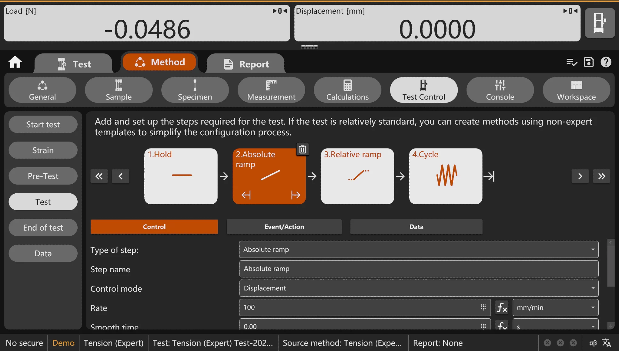
GenTest software supports a method-driven workflow that ties method setup, live data capture, calculations, and the final report into one consistent test record. For NG-SHM Series A testing, this means you can build a controlled test sequence, watch the run in real time, and generate standardized documentation without re-entering data across separate screens or files.
For method setup, GenTest lets you create methods from templates and standards-style examples, then build step-based sequences with defined control logic and changeover conditions. The method also defines the operator inputs, live channels and curves, calculation rules, and report output so execution stays consistent across operators and shifts.
For live monitoring, GenTest provides real-time curve displays commonly used in UTM work, including stress-strain, displacement-load, load-time, and strain-time views. This helps technicians confirm the test is tracking correctly and catch issues like grip seating, extensometer behavior, or unexpected yielding early in the run.
For reporting, GenTest generates reports with tables and graphs, supports flexible units and formula-based expressions, and includes export options that fit Word and Excel documentation workflows and raw data review.
If you want to confirm the best GenTest method template and reporting format for your specific standard and specimen type, review the system details under learn more or request a quote.
Compression platens, bend fixtures, and alignment accessories are typically available for this frame, and they are selected to match your load capacity, specimen geometry, and the specific test method you need to run.
For compression work, the most important fit factors are the platen diameter and thickness, the required surface finish and hardness, and whether you need spherical seating to help manage minor parallelism issues in real-world specimens.
For bend and flexural testing, fixture selection depends on the bend type and span requirements, plus the specimen cross section and expected deflection. The dual-zone layout on this system can also help keep compression tooling mounted while you run tensile tests in the upper zone, which reduces changeover time in busy QC environments.
Alignment accessories are commonly specified when you are chasing tighter repeatability on high-force metallic testing, especially for short-gauge specimens, proof loads, or when you are correlating results across multiple labs. The right approach depends on your grips, adapters, and how your load string is built up.
If you want to confirm the right platen, bend fixture, and alignment stack-up for your specimens and method, use learn more and request a quote.
Spare parts, grips, and wear items are typically available on a priority basis, with the fastest turnaround for common consumables and standard grip components, and longer timelines for specialized or build-to-order items. For high-force servo-hydraulic systems, the exact availability depends on the grip style, jaw insert geometry, load rating, and whether the item is a standard stock component or a custom configuration matched to your specimen and method.
The biggest drivers of delivery time are usually:
- Whether the item is a routine wear component (for example, jaw inserts, seals, or other service consumables) versus a major assembly
- Grip type and interface details, including wedge versus other gripping styles, and any adapter requirements
- Specimen specifics, such as diameter, thickness, surface condition, and expected strength level, which influence jaw selection and insert material
- Any method-driven requirements that affect grip selection, alignment, or extensometry setup
For planned uptime, many labs keep a small on-hand kit of the most-used wear items for their top specimen families, plus a spare set of jaw inserts for each common size range. That approach minimizes downtime when you switch materials or run higher-volume QA lots.
If you want to confirm the right spare set for your exact grip configuration and specimen range, use learn more and then request a quote with your grip type, specimen geometry, and target standards so we can confirm typical lead times and the best spares to stock.
Within the NG-SHM servo-hydraulic family, the A, B, C, D, and DP versions mainly separate by frame architecture and how the test space is laid out. The biggest divider is dual-zone frames, which let you keep a compression setup on the lower platen while running tensile tests in the upper zone, versus single-zone frames, which create one large, uninterrupted space for tension, compression, and fixture-based tests when specimen length and access are the priority.
Series A is the dual-zone, multi-column configuration used when you want fast changeover between routine tensile and compression work without repeatedly tearing down fixtures. It is a strong fit for high-force metallic QA/QC, batch release testing, and labs that run the same methods every day across rebar, plate, bar, tube, and fasteners.
Series B and C are also dual-zone, 6-column frame styles, typically selected when you want that same dual-zone workflow but with a frame layout matched to specific specimen handling needs. Class C is commonly chosen when the gripping area and jaw geometry need to better suit stranded steel wire tensile testing.
Series D and DP use a single-zone frame with the actuator above the test space. This layout is typically preferred for extra-long specimens, high-elongation materials, and setups where you want one open working area for tension, compression, bending, and similar fixture-based tests. DP is a variant that pairs the single-zone concept with a side-action wedge grip approach for tensile work, which can be helpful when access, ergonomics, or gripping workflow drives the decision.
If you want to confirm the best class for your specimen geometry, elongation, and day-to-day changeover needs, use learn more and then request a quote with your material, specimen type, and the grips or fixtures you plan to use.
This universal testing machine is typically configured with layered safeguards to protect the load frame, hydraulics, grips, and operator during high-force testing. In practice, that means the control system can be set up to stop a test automatically if force, stroke, or other monitored conditions approach defined limits, and the machine can be brought to a safe state quickly if something unexpected happens during a run.
Overload protection is usually handled through the test control settings and sensor feedback. The system can be configured with force limits and control-loop monitoring so the test halts before the frame, load cell, or tooling is driven beyond the intended operating window. The exact limit behavior depends on the load capacity selected, the transducers installed, and the test method being run.
Travel limits are commonly implemented as a combination of software travel limits and physical end-of-travel protection. How those limits are set depends on your available stroke, the grips and fixtures in the test space, and whether you are running tension, compression, or proof-load style routines where a hard stop is especially important.
If you want to confirm the right safety limit strategy for your specific capacity, grips, and test methods, use learn more and then request a quote with your specimen geometry and fixture stack-up so we can recommend the safest limit and stop configuration.
Integration of a furnace or environmental chamber with this frame is typically possible, but it depends on how much test-space you need once the chamber is installed and what your temperature method requires.
For high-temperature tensile or compression work, the main fit checks are mechanical. The chamber has to physically fit between the grips or platens, maintain alignment through the hot zone, and still allow the required stroke and specimen access for loading and removal.
It also depends on the measurement and control package you plan to run through the chamber. Common configuration drivers include:
- Specimen type and geometry, including extensometer approach and gauge length access
- Grip style and any water-cooled or high-temperature grip requirements
- Temperature range and stability needs tied to your method, for example ASTM E21
- Routing for thermocouples, chamber interlocks, and safe cable management during crosshead movement
If you want to confirm the right chamber or furnace integration for your specimens and method, use learn more and then request a quote with your specimen drawing, target temperature, and the test standard you are running.
Place the hydraulic power unit in a clean, indoor industrial or lab environment with stable conditions, and give it enough free air volume so the cabinet can reject heat during continuous testing. The HPU on this system uses automatic air cooling that turns on based on oil temperature, so ventilation and clear airflow around the cabinet are important for maintaining oil temperature control and consistent hydraulic performance.
For best results, keep the HPU area free of airborne contaminants and oil-mist sources. The hydraulic circuit uses fine filtration to protect valves and pump components, so minimizing dust, scale, grinding debris, and general shop contamination around the cabinet helps extend filter life and reduces the risk of hydraulic instability.
Plan the layout so the HPU is accessible for routine inspection and service. This HPU is built with a service-friendly enclosure and removable backplate for access to internal components, so leaving working clearance around the cabinet will make maintenance faster and safer.
If you want to confirm the right placement and clearance for your specific HPU configuration and duty cycle, review the system details under learn more or request a quote.
Remote troubleshooting is available, and on-site service can be arranged when the issue requires hands-on support. For most day-to-day problems, the fastest path is typically a remote session by phone or email to isolate whether the root cause is software setup, test method parameters, sensors, hydraulics, or a mechanical adjustment.
Remote diagnostics is especially effective for issues like method setup, control and feedback behavior, load or extension signal checks, and report or data workflow questions. When a repair involves physical inspection, alignment, hydraulic components, grips and fixtures, or safety-related checks, an on-site visit is usually the right next step.
To speed up resolution, have a few basics ready when you reach out, including the machine configuration, the symptom and when it occurs in the test cycle, any alarms or messages, and photos of the setup and gripping arrangement.
If you’re troubleshooting an NG-SHM Series A system and want to confirm the best path for remote diagnostics versus an on-site visit, use learn more and then contact us with your application and current setup details.
This system is available in five load capacity options within the NG-SHM Series A range, spanning 300 kN to 3000 kN.
The available force capacities are:
- 300 kN
- 600 kN
- 1000 kN
- 2000 kN
- 3000 kN
Capacity selection is typically driven by your maximum expected proof load or ultimate load, plus the grip and fixture requirements for your specimen type, for example rebar, plate, bar, tube, or fasteners. If you share your material grade, specimen geometry, and target standard or method, the correct capacity can be sized with appropriate margin.
Periodic verification and calibration for this universal testing machine is typically performed by checking the force measurement system across the working range using traceable reference equipment, then adjusting the system as needed and documenting the results so your lab can demonstrate ongoing class compliance to the applicable force verification standard.
In practice, the verification focuses on the complete force measurement chain used for your tests, not just the frame. That includes the installed force transducer and the controller and data acquisition path used during testing. The NG-SHM Series A is used in standards-driven environments, so the verification approach is commonly aligned with force verification requirements such as ISO 7500-1 and ASTM E4, based on your internal quality system and customer or regulatory expectations.
To keep results consistent between formal calibrations, many labs also run routine in-house checks that match their risk level and workload. Typical elements include:
- Confirming the correct load sensor is selected and zeroed before testing
- Running a short verification check at a few representative force points used in production
- Reviewing any changes in repeatability that could indicate grip seating, alignment, or hydraulic stability issues
If you want to confirm the right verification schedule and documentation package for your specific capacity, load sensor setup, and test standards, use learn more or request a quote.
The NG-SHM Series A provides the following test width (column spacing) between columns by model:
- SHM305: 16.14 in (410 mm)
- SHM605: 17.13 in (435 mm)
- SHM106: 17.72 in (450 mm)
- SHM206: 28.74 in (730 mm)
- SHM306: 20.87 in (530 mm)
Usable clearance in real testing depends on the installed grips, fixtures, and any tooling in the load path. If you share your maximum specimen width, thickness, and intended setup, our team can confirm the best frame and accessory stack-up for reliable clearance throughout the full stroke.
Select the Series A when your lab routinely needs high static force capacity and tight control during metal tensile and compression work, especially when specimen size, strength, or fixture loads push beyond what an electromechanical frame can handle. It is a practical fit for method-driven QA and R&D programs where frame stiffness and stable servo-hydraulic loading directly affect yield, elongation, and stress-strain results.
Series A is commonly justified in labs running medium to large metallic specimens and components such as rebar, heavy plate and bar, fasteners, welded coupons, cast or forged parts, and pipe or tube sections. It is also a strong choice when you need a single platform that can cover both tensile and compression workflows on higher-load materials without constantly reconfiguring the machine around the test type.
Choose Series A specifically when throughput and repeatability matter under high load. The dual test-zone layout supports tension in the upper area and compression in the lower area, and the system is built around a high-stiffness multi-column frame with hydraulic wedge gripping for demanding clamping conditions.
For help matching your specimen geometry, grips, and method requirements to the right Series A configuration, use learn more or request a quote.
Sampling and control performance is managed by the DTC-500 digital controller, which supports sampling and closed-loop control rates up to 1200 Hz for capturing high-force test behavior. This enables stable regulation and consistent data capture for force, displacement, and extension signals during static tensile and compression methods.
In practice, the best rate selection depends on the test type and what you are trying to resolve in the curve. A slow proof load or yield-to-UTS tensile test can run at lower rates, while sudden load changes near fracture, grip seating effects, or short-duration peak events benefit from higher capture rates and a control loop tuned for stability under high stiffness and high load.
If you’d like us to confirm the best sampling and control setup for your method, event duration, and sensor package, please contact our team or request a quote.
For the NG-SHM Series A models, the available maximum test spaces are listed below for both tension (upper test zone) and compression (lower test zone).
Maximum tension and compression test space by model:
- SHM305: Tension 20.47 in (520 mm), Compression 20.47 in (520 mm)
- SHM605: Tension 27.95 in (710 mm), Compression 27.56 in (700 mm)
- SHM106: Tension 29.53 in (750 mm), Compression 25.98 in (660 mm)
- SHM206: Tension 35.43 in (900 mm), Compression 29.53 in (750 mm)
- SHM306: Tension 47.24 in (1200 mm), Compression 39.37 in (1000 mm)
Keep in mind that usable space in real testing depends on the installed grips, compression platens, fixtures, and any extensometer or environmental hardware. If you share your specimen geometry and the fixture stack-up, the frame can be configured so you do not give up needed daylight.
For room-temperature metallic tensile testing, this system supports ISO 6892-1. It also supports ISO 7500-1 for force verification and ISO 9513 for extensometer verification, which are commonly required to document a compliant tensile test setup.
ISO 6892-1 is the primary ISO method for tensile testing of metallic materials at ambient temperature. In practice, meeting the method is not just about the load frame, it also depends on having the right grips for your specimen geometry and the right strain measurement approach for the required yield and elongation results.
If your procedure calls out a specific ISO 6892-1 method option, specimen type, or extensometer class, confirm the exact configuration so the grips, load measurement, and extensometry align with your internal and customer requirements.
This system is a strong fit for rebar tensile verification to EN ISO 15630-1 and similar rebar requirements when configured with the right force capacity, gripping, and strain measurement setup. The NG-SHM Series A is positioned for high-force metallic testing and is listed for EN ISO 15630-1, with typical specimens including reinforcing steel rebar.
For EN ISO 15630-1 work, the key is matching the configuration to your bar size and grade so you can load smoothly through yield and into maximum force without grip slip or jaw damage. In practice, that comes down to selecting the appropriate frame capacity within the 300 kN to 3000 kN range and pairing it with suitable hydraulic wedge grips for ribbed bar.
Method compliance also depends on how you capture elongation and yield behavior. This platform supports extensometer use and closed-loop control, which helps when your procedure calls for controlled loading and consistent strain measurement for reporting.
If you want to confirm the right capacity, grips, and extensometer approach for your rebar diameters and EN ISO 15630-1 reporting needs, use learn more and request a quote.
Closed-loop control is handled by the DTC-500 digital controller, which runs three independent feedback loops so the machine can regulate to a force setpoint, a displacement setpoint, or an extension setpoint, depending on what your method calls for.
In force control, the controller continuously compares the commanded load profile to the live force signal from the load-measuring transducer, then adjusts the servo-hydraulic output to correct any error. This is the mode typically used for proof loading, load holds, and other load-driven steps.
In displacement control, the controller uses position feedback from the machine’s displacement measurement (encoder or grating ruler input) and modulates the actuator to follow a target displacement rate, ramp, or hold. This is commonly used for seating, approach, and certain compression or fixture-driven routines.
In extension control, the controller closes the loop on the extensometer signal so the specimen strain or extension is what drives the actuator response. This is the mode typically selected for yield and elongation-focused tensile methods where strain rate control matters. If you want to confirm the best control mode and sensor configuration for your specific standard and specimen, use learn more or request a quote.
Electrical power and hydraulic utility requirements for the NG-SHM Series A are defined by the selected frame capacity and its matched hydraulic power unit (HPU). The standard power supply for this series is 220 V AC, 50/60 Hz.
Power consumption by model:
- SHM305: 2.5 kW
- SHM605: 3.5 kW
- SHM106: 4 kW
- SHM206: 6 kW
- SHM306: 6 kW
HPU flow rate by model:
- SHM305: 5 L/min
- SHM605: 5 L/min
- SHM106: 5 L/min
- SHM206: 7.2 L/min
- SHM306: 12 L/min
If you’d like us to confirm the best utility plan for your capacity, duty cycle, and grip/fixture package, please contact our team or request a quote.
This system can support common ASTM metallic tension and compression test programs by running standards-based methods in tension and compression, with the final standard coverage depending on your grips, platens, extensometry, and the specific specimen geometry you need to test.
For metallic tensile testing, the NG-SHM Series A is commonly applied to methods such as ASTM E8 and ASTM A370, including production-style verification work on plate, bar, and rebar-type products when the correct gripping and strain measurement setup is selected.
For metallic compression testing, the frame and compression platen setup can be configured to run compression procedures such as ASTM E9, provided the specimen form, alignment approach, and strain or displacement measurement meet your method requirements.
To confirm the exact ASTM tension and compression standards you need to satisfy for your material grade and specimen type, use learn more and request a quote.
The frame is built to handle sustained, high-force testing on large cross-section metal specimens, as long as the machine is sized and configured for your load level and specimen geometry. In the NG-SHM Series A, the multi-column high-stiffness frame is intended to minimize deflection under heavy loads, and the hydraulic power unit includes active cooling to support continuous operation.
For large cross-section work, the practical limit is usually not just the frame, it is the full load train. That includes the selected force capacity, available test space, and the grip or compression fixture package. This series is offered in multiple force capacities, and the listed specimen size ranges vary by model, so the right match depends on what you are pulling or compressing and how long you need to hold near peak load.
If your method includes long holds, proof loads, or repeated high-load cycles, it is worth confirming the exact configuration, including grips, platens, and cooling and hydraulic power unit sizing, against your duty cycle and specimen dimensions.
On-site installation support and operator training for this system are typically available as part of the project scope, especially for high-force servo-hydraulic frames where safe setup and correct method execution matter from day one.
The exact on-site package depends on how your NG-SHM Series A is configured and how you plan to run it. The biggest drivers are the load capacity and hydraulic power unit arrangement, the grips and fixtures you will be using, and your test methods and reporting workflow in the control software.
Most customers use on-site time to get three things locked in: correct mechanical setup and alignment, safe operation and basic maintenance routines, and hands-on training that walks your team through creating and running repeatable tensile or compression tests with your actual specimens.
If you want to confirm what on-site installation and training would look like for your facility and test scope, use the learn more page and then request a quote with your material types, specimen geometry, and the standards you run, and we will map the right commissioning and training plan.
Machine verification requirements such as ISO 7500-1 and ASTM E4 are addressed by configuring the system and its force measurement chain so the frame can be verified to the class and uncertainty your method requires, then documenting that verification as part of your QA program. This universal testing machine is specified for use under ISO and ASTM tensile and compression frameworks, including ISO 7500-1 and ASTM E4, when set up and maintained to the applicable procedure.
In practice, verification is centered on the force indication performance of the complete setup, not just the load frame. That means the load cell, controller settings, hydraulic stability, and the way the machine is loaded in tension and compression all matter, especially on high-force metallic tests where alignment and gripping can influence results.
To keep ISO 7500-1 and ASTM E4 verification straightforward in day-to-day QC, most labs standardize a few items around their typical test range and fixtures:
- Verify in the force ranges you actually use for production and certification testing, not only at full capacity.
- Use the same grip and fixture configurations you run for tensile and compression, since load introduction can affect repeatability.
- Pair force verification with routine checks of extensometer and strain measurement when your method calls for it.
If you want to confirm the right configuration and verification approach for your ISO 7500-1 or ASTM E4 workflow, review the platform details under learn more and share your target force range and test types via request a quote.
Application-specific method templates and practical training are available to help you launch new test programs on this servo-hydraulic universal testing machine, especially when you want consistent, method-driven execution and reporting in GenTest.
Templates are typically set up around your exact test intent, for example tensile, compression, bend, proof load, or rebar verification, then tuned to your method requirements and how you want results calculated and reported. The final setup usually depends on the standard or internal spec you are following, the specimen geometry and expected load range, and the grips, fixtures, and extensometry you will be using.
Training is commonly structured to match the way your lab actually runs tests, so new operators can go from loading a specimen to producing a repeatable report. It can cover items like:
- Method setup and validation checks before releasing a program to production use
- Safe operation and correct specimen alignment and gripping practices
- Running batches, applying pass/fail criteria, and generating consistent reports
If you want to confirm the right template and training scope for your specimens and standards, use learn more and request a quote with your material, specimen drawing, and target standard so we can map the method template and onboarding plan to your workflow.
Related Products
NG-SHM Class DP – Servo-Hydraulic Universal Testing Machine
NG-SHM Class DP is a high-force servo-hydraulic testing machine with an upper actuator, single-zone test space, and side-action hydraulic wedge grips. Available in 600 kN, 1000 kN, and 2000 kN capacities, it supports tension, compression, bending, and shearing tests on metals and structural specimens. Its automatic clamping adjustment, dual-direction grip alignment, precision transducer, and long-travel cylinder help deliver stable, repeatable results.
Read more
NG-SHM Class D – Servo-Hydraulic Universal Testing Machine
NG-SHM Class D is a servo-hydraulic universal testing machine for high-force mechanical testing of metals and structural components. Available in 600 kN, 1000 kN, and 2000 kN capacities, it uses an upper actuator and single-zone test space for tension, compression, bending, and shearing. Its long-travel cylinder, wedge hydraulic grips, and rigid guidance system make it suitable for extra-long, high-elongation specimens.
Read more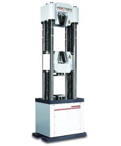
NG-SHM Class C – Servo-Hydraulic Universal Testing Machine
NG-SHM Class C is a servo-hydraulic universal testing machine for high-force metal testing, with capacity options of 600 kN and 1000 kN. Its longer jaw face is designed for tensile testing of stranded steel wire, while the 6-column frame, dual-zone test space, hydraulic wedge grips, quick-return valve, and precision load cell support accurate, repeatable testing of rebar, fasteners, chains, welds, and castings.
Read more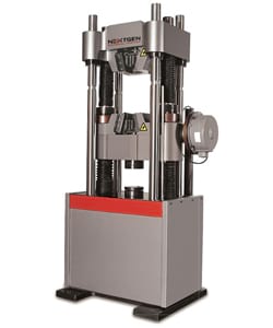
NG-SHM Class B – Servo-Hydraulic Universal Testing Machine
NG-SHM Class B is a high-force servo-hydraulic universal testing machine for tensile, compression, and flexural testing of metals and other high-strength materials. Available from 300 kN to 3000 kN, it uses a rigid multi-column frame, dual-zone test space, hydraulic wedge grips, and precise load-cell measurement to support reliable testing of fasteners, rebar, chains, welds, castings, and structural components.
Read more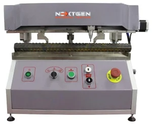
GenMark 500 – Automatic Gauge Length Marking Machine
The GenMark 500 is a full-automatic gauge length marking machine for metal bar, rebar and wire rod, applying the reference marks used to determine elongation after fracture. A servo-driven lead screw sets 5 mm or 10 mm spacing and a pneumatic tungsten steel needle marks specimens up to 500 mm gauge length, supporting ISO 6892-1 and ASTM E8/E8M workflows. Adjustable marking force, quick needle changes, and fixtures for both round and flat samples keep specimen preparation consistent across operators and shifts.
Read more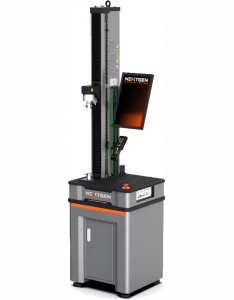
NG-EML Series A – Single-Column Universal Testing Machine (50 N – 5 kN)
NG-EML Series A is a compact single-column benchtop universal testing machine for low-force tensile, compression, and flexural testing. Covering 50 N to 5 kN capacity options, it is suited for rubber, plastics, adhesives, films, foams, wires, metals, composites, and consumer products. Its electromechanical frame, high-speed servo actuation, GenTest software, and standards support make it practical for R&D and routine QC.
Read more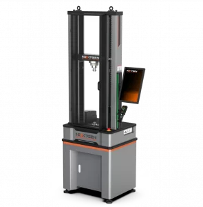
NG-EML Series B – Dual-Column Universal Testing Machine (100 N – 10 kN)
NG-EML Series B is a dual-column benchtop electromechanical universal testing machine for precision testing from 100 N to 10 kN. Built for research and industrial labs, it supports tension, compression, flexural, and component testing of composites, high-strength metals, polymers, films, foams, and rubber. Its compact rigid frame, advanced control accuracy, and GenTest software help deliver repeatable results in limited lab space.
Read more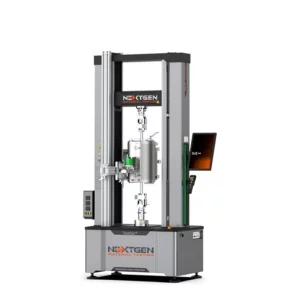
NG-EML Series C – Dual-Column Universal Testing Machine (5–50 kN)
NG-EML Series C is a dual-column electromechanical universal testing machine available in bench-top and floor-standing formats from 5 kN to 50 kN. Built for tension, compression, flexural, shear, and peel testing, it combines Class 0.5 accuracy, a servo direct-drive system, high-rigidity frame, touchscreen control, and GenTest software to support precise testing of metals, composites, rubber, plastics, and polymers.
Read more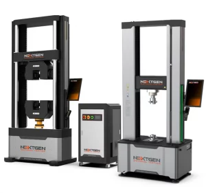
NG-EML Series D – Floor-Standing Universal Testing Machine (50–1000 kN)
NG-EML Series D is a heavy-duty floor-standing electromechanical universal testing machine for high-capacity tensile, compression, and flexural testing. Available from 50 kN to 1000 kN, it is built for high-strength steels, advanced composites, alloys, and challenging research materials. Its rigid dual-column frame, servo direct-drive system, closed-loop control, safety protections, and GenTest software support stable, accurate testing.
Read more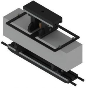
Flexure Fixtures for Large and Brittle Specimens
These flexure fixtures are designed for precise bending tests on large, brittle, or high-strength specimens, including metals, ceramics, composites, concrete, and construction materials. Compatible with hydraulic universal testing machines, they support single-point, three-point, and four-point bending configurations with adjustable spans and roller supports. Capacities up to 2000 kN help laboratories evaluate flexural strength, deformation behavior, and structural integrity.
Read more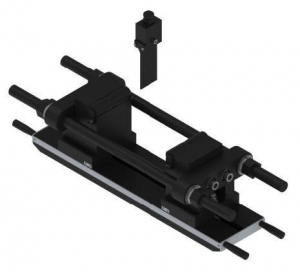
Heavy-Duty Bending Fixtures for Hydraulic Flexural Testing
Heavy-duty bending fixtures support high-force flexural testing of metals, composites, ceramics, reinforcing bars, and structural materials on hydraulic universal testing machines. Designed for loads up to 2000 kN, they use secure fixing blocks, positioning-pin connections, adjustable mandrel options, and wide test spaces to maintain stability. GB/T 232, GB1499.1, and GB1499.2 compliance helps laboratories perform accurate, repeatable bend evaluations.
Read more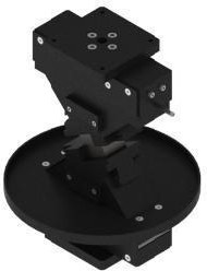
Splitting Fixtures for Rock and Concrete Testing
Splitting fixtures for indirect tensile testing are designed for rock, concrete, and composite specimens tested on hydraulic universal testing machines. Built for demanding geotechnical, mining, and structural-materials laboratories, they provide stable specimen support, rugged construction, and secure mounting under high loads. Compatibility with cylindrical and cubic samples, GB/T 23561.11 alignment, and capacities up to 2000 kN support repeatable shear and splitting evaluations.
Read more