NG-SHM Class B – Servo-Hydraulic Universal Testing Machine

Metal Testing Equipment
Standards




NG-SHM Class B Servo Hydraulic Testing Machine
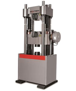
The NG-SHM Class B series is designed to provide a solution for your high-force mechanical testing of a diverse range of materials covering many different industries. Class B has been designed around the application of testing fasteners, rebar, chains, welds and castings and uses a "worm wheel" driven cross head to adjust the test space.
Force Capacity: 300kN (67442.68 lbf), 600kN (134885.36 lbf), 1000kN (224808.94 lbf), 3000kN (674426.82 lbf)
Load Frame Configuration: 6 column, servo-controlled hydraulic
Test Space: Dual zone (tension on top, compression on bottom)
Load Frame
- Lead screw driven crosshead to adjust the test space
- Durable 6-column load frame design incorporates 3-position crosshead, adjustable specimen positioning, precision guide columns, thick crosshead and a base beam minimizes the load frames stored energy while producing reliable, stable, accurate loads, strain and modulus values.
- Ergonomically designed load frames ensure safety, reduce operator fatigue, and provide the highest level of flexibility.
- Standard Dual Zone Test Space for reducing setup time
- "Quick Return" hydraulic valve for higher throughput
- Automatic limit checking for crosshead position, overload, over temperature, over voltage, etc.
- The system can return automatically, the oil cylinder can return to the original position manually or automatically after finishing testing
- Positive specimen holding is ensured by the wedge action hydraulic operated grips
- Encoder mounted on the seat is for position measurement of the crosshead to provide higher accuracy
- Servo valve provides high stability and reliability
Load Cell
- Uses strain gauge load cell technology to measure the force being applied to your specimen. The load cell is located in the lower grip and is used to directly measure tensile force.
- Precise load cell measures and captures sensitively tension and compression force, high accuracy load measurement resolution reaches 1/350000.
- Quality load cell ensures high precision and repeatability.
NG-SHM Class B - Servo Hydraulic Testing Machine Technical Specifications
| Servo-Hydraulic Universal Testing Machine | ||||
|---|---|---|---|---|
| Model | SHM305 | SHM605 | SHM106 | SHM306 |
| Class | Class B | |||
| Capacity | 300kN (67442.68 lbf) | 600kN (134885.36 lbf) | 1000kN (224808.94 lbf) | 3000kN (674426.82 lbf) |
| Calibration accuracy | Class 1 / Class 0.5 | |||
| Force range | 1% - 100%FS | |||
| Force accuracy | Better than ±1%/±0.5% | |||
| Extension Range | 1% - 100%FS | |||
| Extension Accuracy | Better than ±1%/±0.5% | |||
| Extension Resolution | 1/350000 of max extension | |||
| Actuator (piston) speed (mm/min) | 0 - 180 | 0 - 140 | 0 - 90 | 0 - 80 |
| Force Loading Speed | 0.02% - 2% FS /s | |||
| Column Number | 4 | 6 | 6 | 6 |
| Column Spacing (test space width) (cm) | 40.5 | 43 | 43 | 95 |
| Maximum Tension Space (cm) | 53 | 75 | 80 | 120 |
| Maximum Compression Space (cm) | 50 | 60 | 70 | 100 |
| Diameter of Round Specimens (mm) | ?10 - ?32 | ?10 - ?40 | ?15 - ?60 | ?30 - ?110 |
| Diameter of Threaded Steel (mm) | ?10 - ?32 | ?10 - ?36 | ?10 - ?40 | - |
| Thickness of Flat Specimens (mm) | 2 - 25 | 2 - 30 | 2 - 40 | 10 - 100 |
| Compression Platens (cm) | ?12 | ?15 | 20 x 20 | ?28 |
| Actuator (piston) Stroke (cm) | 15 | 20 | 25 | 30 |
| Frame Dimensions (l x w x h) (cm) | 94 x 61 x 200 | 112 x 77 x 260 | 125 x 92 x 280 | 132 x 95 x 400 |
| Hydraulic Power Unit Dimensions (l x w x h) (cm) | 45.5" x 24" x 35.5" / 45.3 × 23.6 × 35.4″ (115 x 60 x 90 cm) | |||
| Power Consumption (kW) | 5 | 6 | 8 | 6.5 |
| Frame Weight (kg) | 4409.24 lbs / 2000 kg | 6613.86 lbs / 3000 kg | 11023.11 lbs / 5000 kg | 24250.84 lbs / 11000 kg |
For Laboratories
Need Additional Quality Control Equipment to Build Your Laboratory?
Servo-hydraulic universal testing is only one part of a complete quality control laboratory. NextGen can help you equip your entire lab with impact testers, notching and broaching systems, cooling chambers, tensile testers, hardness testers, specimen preparation equipment, and other supporting solutions, all coordinated as one complete project.
- One partner to equip your complete laboratory
- Installation, training, calibration
- Support for the life of the equipment
FAQs
The NG-SHM Class B is a servo-hydraulic universal testing machine for high-force work. We designed the series around the applications that dominate a component laboratory: fasteners, rebar, chains, welds and castings.
That is a different job from testing prepared coupons. Components fail suddenly and at high load, the geometry is rarely ideal, and the machine has to hold the specimen securely enough that the failure happens in the part rather than in the grips.
Four capacities are offered, from 300 kN (67,442 lbf) to 3000 kN (674,426 lbf), each with its own test space and specimen range. The frame is built with a thick crosshead, precision guide columns and a base beam that keeps the energy stored in the frame low, which matters when a fastener lets go at full load.
The rest of the range sits in our servo-hydraulic machines.
Fasteners, rebar, chains, welds and castings are the applications the series was designed around.
What they have in common is high force at relatively short extension and a violent release of energy when the specimen finally lets go. The design answers that directly: a durable six-column style frame, a three-position crosshead, adjustable specimen positioning and a base beam that minimises stored energy while still producing stable load, strain and modulus values.
Beyond components, the same frame runs routine tensile work on metallic specimens to ASTM E8 and ISO 6892-1 when it is fitted with the appropriate grips and an extensometer.
If your work sits across both, tell us the mix when you enquire and we will specify the grips accordingly rather than quoting a frame alone.
Four capacities are offered: 300 kN (67,442 lbf), 600 kN (134,885 lbf), 1000 kN (224,808 lbf) and 3000 kN (674,426 lbf), sold as models SHM305, SHM605, SHM106 and SHM306.
Capacity should be chosen from the strongest specimen you expect, with headroom above it. A machine asked to work at the very top of its range on every test is the one that loses its calibration first, and it leaves nothing in reserve when a batch of material comes in stronger than the drawing suggested.
The opposite mistake is just as common. Buying far more capacity than the work requires pushes routine tests toward the bottom of the verified range, where the permitted error is largest in relative terms.
If the load you need sits between two models, send the specimen and the standard with a quotation request and our team will size it with you.
The test space grows with the capacity. Column spacing runs 40.5, 43, 43 and 37.4″ (95 cm); maximum tension space 53, 75, 80 and 47.2″ (120 cm); maximum compression space 50, 60, 70 and 39.4″ (100 cm) across the four models.
Piston stroke follows the same pattern at 15, 20, 25 and 11.8″ (30 cm), and piston speed falls as the cylinder grows: 0 to 7.1″ (180 mm)/min on the SHM305 down to 0 to 80 mm/min on the SHM306. Power consumption and frame weight rise with size as well, which is what makes the installation of the largest model a different exercise from the smallest.
Every model keeps the same accuracy class, the same measurement resolution and the same dual zone layout, so the choice is about specimen size and force rather than about capability.
The Class C and Class D frames differ in the layout itself, which is a separate decision.
A dual zone frame provides two working spaces: tension above the crosshead and compression below it. It is standard on the Class B.
The benefit is setup time. A laboratory that alternates between pulling rebar and crushing a casting does not have to strip the tensile grips out of the frame to make room for platens, because both are rigged at once and the machine moves between them. Tensile testing to ASTM E8 and compression work can therefore share a shift without a fixture change between every specimen.
For a busy component laboratory that is usually worth more than any single specification on the data sheet, because the time lost to rigging is larger than the time spent testing.
Machines built the other way, with one large space serving every test type, are the Class D layout.
Round specimens are covered from Ø10 to Ø32 mm on the SHM305, Ø10 to Ø40 mm on the SHM605, Ø15 to Ø60 mm on the SHM106 and Ø30 to Ø4.3″ (110 mm) on the SHM306.
Flat specimens run 2 to 25 mm thick, 2 to 30 mm, 2 to 40 mm and 10 to 3.9″ (100 mm) across the same four models. Threaded steel is covered to Ø32, Ø36 and Ø40 mm on the first three models.
These ranges are set by the grips as much as by the frame, which is why we quote them together. A specimen at the very bottom of a range is often better tested on the next size down, where the jaws close on a proportionate area and the load sits comfortably inside the verified range.
Send the largest section you test with a request for pricing and we will confirm the model and the grips as one specification.
Yes. Rebar is one of the applications the series was designed around, and threaded steel is quoted to Ø32, Ø36 and Ø40 mm depending on the model.
The part that decides success is the grip rather than the frame. Ribbed bar needs a wedge that bites without shearing the ribs off, and a grip that slips on a ribbed surface produces a low result and a dangerous release of energy at the same time. The machine uses wedge action hydraulic grips as standard for exactly this reason.
Rebar is normally reported together with the tensile properties of the steel itself, which is ISO 6892-1 territory, and often alongside a bend test that the same frame can perform with the appropriate fixture.
Tell us the bar sizes and the standard you report to and we will confirm the configuration.
The machine is calibrated to Class 1 or Class 0.5, the accuracy classes defined in ISO 7500-1 for the force measurement of a testing machine.
The class states how far the indicated force may deviate from the true force. Class 0.5 halves the permitted error of Class 1, and it is the number an auditor or a customer looks at first when a result is challenged.
Which class a laboratory needs is usually decided by its accreditation and by the specifications it reports against rather than by preference. Where a testing house serves several customers, the stricter class is the safer purchase because it covers both cases.
The North American equivalent of that verification procedure is ASTM E4, and we can supply the machine prepared for either.
Force range is 1% to 100% of full scale, with accuracy better than ±1% or ±0.5% depending on the calibration class.
The lower limit matters as much as the upper one. Below 1% of full scale the reading falls outside the verified range of the machine, which is why a 3000 kN frame is the wrong tool for a small fastener even though it will physically hold it and return a number.
This is the single most common specification mistake we see in enquiries. A laboratory sizes the machine for the heaviest test it might ever run and then discovers that its routine work sits below the verified window.
Where the range of work is genuinely wide, the answer is usually two frames or a second load cell rather than one very large machine, and we are happy to work through that with you before you commit.
Resolution is 1/350,000 of the maximum, for both force and extension.
On a 1000 kN machine that is a step of under 3 N. Resolution is not the same thing as accuracy: it describes the smallest change the system can display, while accuracy describes how close the reading is to the truth.
It still matters, because a coarse resolution puts a floor under the noise in a curve. A yield point read from a stepped curve is not defensible, and modulus calculated from a coarse elastic region is worse still.
For most component work the practical benefit is a clean curve that a customer can read without explanation, which is what a test report is for.
The machine uses strain gauge load cell technology, and the cell is located in the lower grip so that tensile force is measured directly on the specimen.
Measuring at the specimen rather than through the frame keeps friction in the crosshead and in the hydraulic seals out of the reading. That friction is not constant, it changes with speed, temperature and wear, and a machine that measures through it drifts in ways that are hard to diagnose.
The load cell captures both tension and compression, and the measurement resolution reaches 1/350,000 of the maximum.
The cell is verified with the machine as a complete system, to the classes of ISO 7500-1, rather than on its own.
Extension range is 1% to 100% of full scale with accuracy better than ±1% or ±0.5%, matching the force class, and extension resolution is 1/350,000 of maximum extension.
Displacement is measured by an encoder mounted on the seat, which reads the actual crosshead position rather than inferring it from the hydraulics. That distinction matters on a servo-hydraulic machine, where oil compressibility and seal behaviour would otherwise appear in the number.
For elongation itself an extensometer remains the instrument of record. Crosshead travel includes the take-up of the grips and the elastic stretch of the frame, and on a short specimen that is a large share of the total.
We can quote the frame with a suitable extensometer for the standards you report to.
Force loading speed runs from 0.02% to 2% of full scale per second.
That window is what standards mean when they specify a controlled rate. ISO 6892-1 and its ASTM equivalent both put limits on how quickly stress may be applied, because the yield strength a metal reports depends on the rate at which it is loaded.
In practice the low end of the range is the important one. Holding a slow, steady rate through the elastic region is harder for a hydraulic machine than moving quickly, and it is where the quality of the servo valve and the control loop shows.
If your specification names a stress rate, send it to us and we will confirm that the model you are considering covers it across the whole range of your specimens.
Piston speed runs from 0 to 7.1″ (180 mm)/min on the SHM305, 0 to 5.5″ (140 mm)/min on the SHM605, 0 to 90 mm/min on the SHM106 and 0 to 80 mm/min on the SHM306.
The upper figure is a positioning speed rather than a test speed. It decides how long an operator waits between specimens while the piston travels to the start position, and on a machine running a full day of components that waiting time adds up to a measurable part of the shift.
Test rates themselves are set by the force loading speed and by the control mode chosen in the software, not by the maximum piston speed.
Where throughput is the priority, the quick return valve fitted to the machine matters more than the headline speed.
The quick return hydraulic valve returns the cylinder faster between tests, which is a throughput feature rather than a measurement one.
After a specimen breaks, the piston has to travel back before the next one can be loaded. On a 11.8″ (300 mm) stroke at test speed that return would dominate the working day, so the hydraulic circuit provides a separate fast path for it.
For a laboratory doing batch release work on fasteners or rebar, where dozens of specimens are run to the same method, this is one of the features that decides how many tests fit into a shift.
It works alongside the automatic return function, so the machine can reset itself while the operator is clearing and reloading.
It can. The system returns automatically, and the oil cylinder can also be returned to its original position manually once the test has finished.
Both modes earn their place in a component laboratory. Automatic return keeps a repetitive batch moving without the operator intervening between specimens, which is the normal case for routine release testing.
Manual return gives the operator control when the situation is not routine: a broken fastener wedged in the jaws, a specimen that has to be recovered intact for examination, or a fixture that needs clearing before anything moves.
Having both is what allows the same machine to run production testing in the morning and investigative work in the afternoon.
The machine checks its own limits automatically, covering crosshead position, overload, over temperature and over voltage.
High-force hydraulic testing is one of the few laboratory activities where a mistake is dangerous rather than merely expensive. A 3000 kN frame stores a great deal of energy at full load, and the limits are there to stop the machine before the frame, the fixture or the operator finds the problem.
The mechanical design contributes as well: a three-position crosshead, precision guide columns and a base beam that minimises stored energy all reduce what is released when a specimen fails.
We recommend that these functions form part of the operator training at installation rather than being discovered from the manual afterwards.
The machine uses wedge action hydraulic grips, which hold the specimen positively instead of relying on a mechanical clamp being tightened by hand.
The higher the load, the more the grip decides the outcome of the test. A specimen that slips gives a low reading and no warning that it did so; a specimen crushed at the jaw fails at the grip rather than in the gauge length, and that result has to be discarded.
Wedge grips tighten as the load rises, so the clamping force follows the test rather than being set once at the start. On high strength steel that is the difference between a valid result and a wasted specimen.
Grip selection depends on the specimen, so we quote grips with the frame rather than separately.
The servo valve converts a command from the control system into oil flow, and it is the reason the machine holds a stable rate instead of surging.
A valve with high stability and reliability is what makes genuine closed-loop control possible: force, position or extension can be the controlled variable, and the valve corrects hundreds of times a second to hold whichever one the method has selected.
That capability is what standards assume when they specify a stress rate or a strain rate. Without it the machine can only be driven at a fixed valve opening, which is not the same thing at all once the specimen starts to yield.
Clean oil is what keeps a servo valve working, which is why filtration and oil condition are the maintenance items worth attention on any hydraulic machine.
Our GenTest software runs the NextGen servo-hydraulic and electromechanical frames.
Tests are executed from defined methods, so the setup parameters, the recorded data, the calculations and the report all stay tied to the same test record. For a laboratory reporting to a customer, that traceability is worth more than any single feature of the frame itself.
It also removes a common source of dispute. When the method is the same file every time, two operators on two shifts produce results that can be compared, and a result questioned six months later can be traced back to the exact conditions that produced it.
The same software runs across a mixed laboratory, so a site with several frames keeps one set of methods rather than one per machine.
Power consumption is 5 kW on the SHM305, 6 kW on the SHM605, 8 kW on the SHM106 and 6.5 kW on the SHM306.
The hydraulic power unit is what draws it, and it runs whenever the machine is pressurised rather than only during a test. A laboratory that leaves the machine running between specimens should plan for that continuous load rather than for the peak alone.
It is worth confirming the figure against the supply that serves the laboratory before the machine arrives, particularly where other equipment shares the same circuit.
Tell us the supply available and our team will confirm what the installation requires.
The hydraulic power unit measures 45.5 x 24 x 35.5 in (115 x 60 x 90 cm) on every model.
It stands separately from the load frame, so the floor plan has to allow for both units plus the hose run between them. That separation is deliberate: it keeps the heat and the noise of the pump away from the frame and the operator.
Keep service access to the unit clear when you plan the layout. Oil and filters are the recurring maintenance items on any hydraulic machine, and a power unit boxed into a corner turns a routine job into a lifting operation.
We can review the proposed layout with you before delivery if the space is tight.
Frames measure 37 × 24 × 78.7″ (94 x 61 x 200 cm), 44.1 × 30.3 × 102″ (112 x 77 x 260 cm), 49.2 × 36.2 × 110″ (125 x 92 x 280 cm) and 52 × 37.4 × 157″ (132 x 95 x 400 cm) across the four models.
Weights are 4,409 lbs (2,000 kg), 6,613 lbs (3,000 kg), 11,023 lbs (5,000 kg) and 24,250 lbs (11,000 kg). The 3000 kN model is four metres tall and eleven tonnes, so ceiling height, door clearance and floor loading are settled before anything else in the specification.
Access for installation matters as much as the final position. A frame of this size arrives in one piece and needs a route into the building as well as a place to stand.
Our team will go through the site requirements with you as part of the quotation rather than after the order.
Compression platens are Ø4.7″ (12 cm) on the SHM305, Ø5.9″ (15 cm) on the SHM605, 7.9 × 7.9″ (20 x 20 cm) on the SHM106 and Ø11″ (28 cm) on the SHM306.
Platen size is what limits the compression side of the dual zone space. A casting or a block wider than the platen cannot be loaded squarely, and an off-centre compression test loads the frame and the columns as well as the specimen.
Where compression work is a significant part of the laboratory's programme, the platen size is worth checking against the largest part you expect before the model is chosen, because it is easier to select the right frame than to work around a small platen afterwards.
Tell us what you compress and we will confirm the platen supplied with each option.
Hydraulics deliver high force from a comparatively compact frame, which is why component testing above a few hundred kilonewtons is almost always hydraulic.
Electromechanical frames are quieter, cleaner and better suited to very low forces and very slow rates, and they need no hydraulic power unit, oil or filtration. Below about 100 kN they are usually the better laboratory instrument.
The dividing line in practice is the load and the specimen. For fasteners, rebar, chain, welds and castings the hydraulic frame is the correct tool; for thin sheet, plastics, textiles and small components the electromechanical machine is.
Both families sit side by side in our universal testing machines range and both run the same software, so a laboratory can operate one of each without maintaining two sets of methods.
Force verification follows ISO 7500-1 or ASTM E4, the standards that define how a testing machine is checked against reference equipment and what accuracy class it is then assigned.
Verification is periodic rather than a one-off event. The class stated on a certificate describes the machine on the day it was checked, which is why laboratories schedule it alongside the rest of their calibration programme and why an accreditation body will ask to see the interval as well as the certificate.
Anything that changes the load path can affect the result: a new load cell, a significant repair, or moving the machine to another site.
We can arrange verification with the installation so that the machine enters service with a current certificate rather than waiting for one.
Related Products
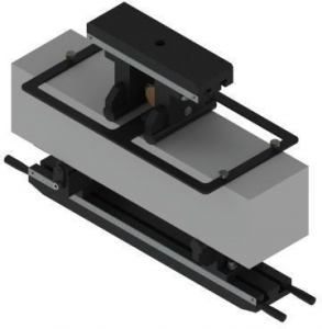
Flexure Fixtures for Large and Brittle Specimens
These flexure fixtures are designed for precise bending tests on large, brittle, or high-strength specimens, including metals, ceramics, composites, concrete, and construction materials. Compatible with hydraulic universal testing machines, they support single-point, three-point, and four-point bending configurations with adjustable spans and roller supports. Capacities up to 2000 kN help laboratories evaluate flexural strength, deformation behavior, and structural integrity.
Read more
Grips and Fixtures for Hydraulic Universal Testing Machines
Grips and fixtures for hydraulic universal testing machines are built for high-force tensile, shear, proof load, flexural, splitting, and structural component testing. Designed for NextGen servo-hydraulic UTMs, these accessories integrate with hydraulic clamping systems and support demanding applications involving fasteners, composites, welding mesh, rock, concrete, and large specimens. ASTM, ISO, DIN, JIS, and GB/T compatibility helps laboratories maintain repeatable, standards-based workflows.
Read more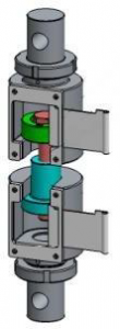
Threaded Grips for Bolt and Nut Testing
Threaded grips for bolt and nut tensile testing provide secure axial loading for bolts, studs, nuts, and other threaded fasteners. Designed for universal testing machines, they help prevent slippage, thread stripping, and misalignment during high-force tests. Compatibility with ASTM F606, ISO 898, DIN 50125, and multiple metric thread sizes makes them useful for construction, automotive, aerospace, manufacturing, and fastener QC applications.
Read more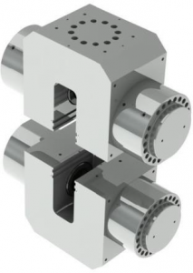
Dual-Action Hydraulic Wedge Grips for High-Capacity Testing
Dual-Action Hydraulic Grips are high-capacity wedge-clamping fixtures for tensile testing on universal testing machines. Designed for metals, plastics, and composite specimens, they apply uniform hydraulic pressure to reduce slippage, deformation, and grip-end failures during demanding tests. Interchangeable jaw faces, hydraulic power-unit actuation, UTM compatibility, and support for ASTM, ISO, DIN, JIS, and GB/T workflows help laboratories improve safety and repeatability.
Read more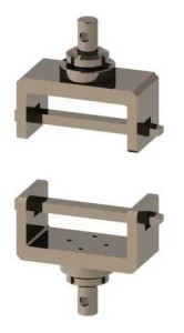
Specialized Grips and Fixtures for Tear, Peel and Puncture Testing
These specialized grips and fixtures expand UTM testing capabilities for tear, peel, puncture, shear, and unique tensile applications. They are suitable for plastic films, nonwovens, geotextiles, footwear components, waterproof roll materials, safety nets, buckles, eyes, and sandwich structures. ASTM D624, ASTM D1004, ISO 34, ISO 3303, and related standards support reliable force measurement across packaging, textile, construction, and materials testing workflows.
Read more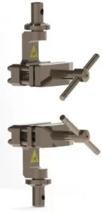
TestStar Series Grips and Fixtures for Hydraulic UTMs
TestStar® Series grips and fixtures are high-precision accessories for integrating tensile, snubbing, wedge-action, pneumatic, compression, and bending setups with hydraulic and electromechanical universal testing machines. Built for metals, polymers, composites, geotextiles, and demanding industrial specimens, the series emphasizes rigid construction, quick interchangeability, ergonomic handling, and compatibility with ASTM, ISO, DIN, and related standards for repeatable mechanical testing.
Read more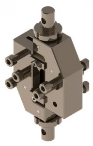
Composite Grips and Fixtures for Tensile and Shear Testing
Composite grips and fixtures are engineered for tensile, compression, shear, bending, peel, and delamination testing of fiber-reinforced plastics, carbon composites, laminates, and hybrid materials. Designed for NextGen universal testing machines, they support standards such as ASTM D3039, ISO 527, ASTM D2344, ISO 14125, and DIN EN 2562. These fixtures help labs generate repeatable data for R&D, QA, and compliance testing.
Read more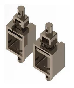
Grips and Fixtures for Wood Testing
These wood testing grips and fixtures support tensile, shear, flexural, internal bond, and fastener-related evaluation of engineered wood, panels, boards, and structural assemblies. Designed for use with NextGen NG-EML and NG-SHM universal testing machines, they help laboratories characterize wood behavior under standardized loading conditions. ASTM D198, ISO 3349, ISO 3340, and GB/T 1936.1 compatibility supports reliable research and QC workflows.
Read more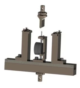
3-Point and 4-Point Bending Fixtures for Flexural Testing
These 3-point and 4-point bending fixtures support flexural strength, deformation, and modulus testing of natural stone, ceramics, composites, concrete, metals, bricks, and other structural or brittle materials. Adjustable upper and lower spans, roller-supported loading, multiple capacity options, and optional deformation measurement help laboratories perform standardized bending tests with stable support conditions and repeatable force application.
Read more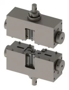
Wedge Tensile Grips for Metals and Composites
Wedge tensile grips are built for high-load tensile testing of flat and round specimens made from metals, composites, and plastics. Their wedge-action mechanism increases gripping pressure as tensile force rises, helping minimize slippage and maintain alignment during demanding tests. Available models support force capacities from lower-force laboratory work up to 300 kN, with interchangeable flat and vee jaw inserts for different specimen sizes.
Read more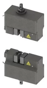
Pneumatic Grips for Fast and Repeatable Clamping
Pneumatic grips provide fast, repeatable air-actuated clamping for universal testing machines in high-throughput tensile and compression workflows. Designed for wires, composites, polymers, films, fabrics, and other materials, they apply uniform gripping pressure while reducing operator fatigue and sample loading time. Side-action, wedge-action, and snubbing configurations, plus interchangeable jaw faces, support secure holding across varied specimen geometries and standards.
Read more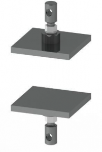
Shoulder Fixtures for Pull-Off Testing
Shoulder fixtures are specialized tensile grips for specimens and components with shoulder geometries, where alignment and secure seating are essential for reliable pull-off or tensile testing. Compatible with NG-EML and SHM universal testing machines, they help laboratories reduce bending effects, improve repeatability, and support standardized ASTM and ISO workflows in research, production, and quality-control environments.
Read more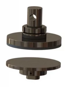
Compression Fixtures for Rigid Samples
Compression fixtures provide aligned axial loading for rigid samples tested on NG-EML and SHM universal testing machines. They are suited for metals, polymers, elastomers, foams, composites, and construction materials where stable force distribution and specimen alignment are critical. High-rigidity construction, secure contact surfaces, and compatibility with ASTM D695, ISO 604, ASTM E9, and GB/T 14485 support repeatable compression testing.
Read more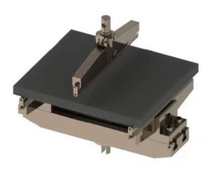
3-Point Bending Fixtures for Flexural Testing
These bending fixtures support standard 3-point flexural testing of plastics, composites, metals, ceramics, alloys, and construction materials. Designed for use with NG-EML and SHM universal testing machines, they offer adjustable spans, multiple capacity options, and repeatable roller-supported loading. Compatibility with ASTM D790, ISO 178, ISO 14125, ASTM E290, and GB/T 9341 helps laboratories perform consistent standards-based flexural evaluations.
Read more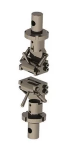
Eccentric Roller Grips for Thin and Flexible Specimens
Eccentric roller grips are built for low-force tensile testing of thin, soft, and flexible specimens such as rubber sheets, plastic film, and deformable materials. Their cam-driven roller mechanism increases clamping pressure as tensile load rises, helping prevent slippage without damaging delicate surfaces. Compatible with NextGen NG-EML and SHM systems, they support repeatable alignment and accurate testing of narrow specimens.
Read more
Self-Tightening Grips for Elastic Materials
Self-tightening grips are designed for tensile testing of deformable, elastic, or low-friction materials such as rubber, plastics, foams, textiles, and biomedical specimens. As tensile force increases, the gripping mechanism automatically increases clamping pressure, helping compensate for thinning or elongation during the test. This reduces slippage, limits specimen damage, and improves repeatability without frequent manual adjustment.
Read more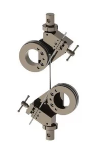
Snubbing Grips for Wire and Cable Testing
Snubbing grips, also known as capstan grips, are designed for tensile testing of wires, cables, ropes, textile strips, and geogrids that can slip or break in standard clamps. By wrapping the specimen around curved surfaces, they increase friction and reduce grip-end failures. These fixtures help laboratories achieve safer, more repeatable axial loading for high-strength or flexible materials.
Read more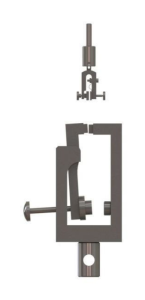
Side-Action Tensile Grips
Side action tensile grips provide quick, secure clamping for films, thin sheets, textiles, fine wires, polymer strips, and other flexible specimens on universal testing machines. Available in manual lever and screw-action configurations, they support different force ranges, jaw surfaces, and specimen sizes. Their side-clamping design helps improve alignment, reduce slippage, and speed up routine tensile testing in QC and R&D labs.
Read more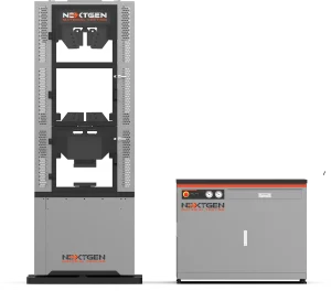
NG-SHM Series A – Servo-Hydraulic Universal Testing Machine (300–3000 kN)
NG-SHM Series A is a high-force servo-hydraulic universal testing machine for static mechanical testing of metals and structural components. Available from 300 kN to 3000 kN, it uses a high-stiffness multi-column frame and dual-zone layout for tensile and compression work. Hydraulic wedge grips, extensometer compatibility, and GenTest software support testing of rebar, fasteners, chains, welds, castings, and large metallic specimens.
Read more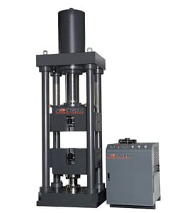
NG-SHM Class DP – Servo-Hydraulic Universal Testing Machine
NG-SHM Class DP is a high-force servo-hydraulic testing machine with an upper actuator, single-zone test space, and side-action hydraulic wedge grips. Available in 600 kN, 1000 kN, and 2000 kN capacities, it supports tension, compression, bending, and shearing tests on metals and structural specimens. Its automatic clamping adjustment, dual-direction grip alignment, precision transducer, and long-travel cylinder help deliver stable, repeatable results.
Read more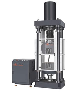
NG-SHM Class D – Servo-Hydraulic Universal Testing Machine
NG-SHM Class D is a servo-hydraulic universal testing machine for high-force mechanical testing of metals and structural components. Available in 600 kN, 1000 kN, and 2000 kN capacities, it uses an upper actuator and single-zone test space for tension, compression, bending, and shearing. Its long-travel cylinder, wedge hydraulic grips, and rigid guidance system make it suitable for extra-long, high-elongation specimens.
Read more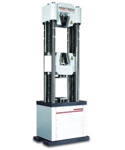
NG-SHM Class C – Servo-Hydraulic Universal Testing Machine
NG-SHM Class C is a servo-hydraulic universal testing machine for high-force metal testing, with capacity options of 600 kN and 1000 kN. Its longer jaw face is designed for tensile testing of stranded steel wire, while the 6-column frame, dual-zone test space, hydraulic wedge grips, quick-return valve, and precision load cell support accurate, repeatable testing of rebar, fasteners, chains, welds, and castings.
Read more
GenTest v3.0 Software for Universal Testing Machines
GenTest v3.0 is NextGen’s data acquisition and test control software for universal testing machines, built around method-driven workflows for tensile, compression, and flexural testing. It connects setup parameters, live channels, curves, calculations, recorded data, and report outputs within one test record, helping laboratories standardize operator inputs, control steps, results review, and documentation across servo-hydraulic and electromechanical UTM stations.
Read more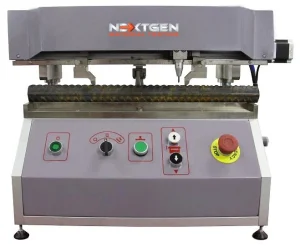
GenMark 500 – Automatic Gauge Length Marking Machine
The GenMark 500 is a full-automatic gauge length marking machine for metal bar, rebar and wire rod, applying the reference marks used to determine elongation after fracture. A servo-driven lead screw sets 5 mm or 10 mm spacing and a pneumatic tungsten steel needle marks specimens up to 500 mm gauge length, supporting ISO 6892-1 and ASTM E8/E8M workflows. Adjustable marking force, quick needle changes, and fixtures for both round and flat samples keep specimen preparation consistent across operators and shifts.
Read more