Standards
Accurate Tensile Testing of Fasteners with NextGen UTM Grips
NextGen offers a specialized range of bolt and nut tensile grips designed for accurate tensile testing of threaded fasteners using universal testing machines (UTMs). These fixtures provide secure clamping and axial loading for bolts, studs, and nuts, for reliable testing under standardized procedures. The design accommodates high tensile forces while preventing slippage or thread stripping. All grips are engineered to meet international standards including ASTM F606, ISO 898, and DIN 50125, and are compatible with most industry test configurations.
This equipment is suited to quality control and research applications in sectors such as construction, automotive, aerospace, and manufacturing, where threaded fastener performance must be validated. Whether you are testing according to ISO, ASTM, or DIN protocols, these grips support compliance with precision and repeatability.
Bolt and Nut Tensile Grip Models
Two grips cover the range. They differ in force capacity, in the pin that mounts them and in the thread sizes they accept, so the choice follows the fastener you test and the frame you run it on. Each grip is listed with its own specification table, and the optional bushings, thimbles, wedges and mandrels that go with it follow underneath.
Model NGA105A
Bolt and Nut Tensile Grip
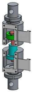
The NGA105A Bolt and Nut Tensile Grip is built for tensile testing of bolts and nuts, for compliance with GB/T 3098.1-2010 standards. With a 100 kN load capacity and compact structure, it’s suited to precision testing of fasteners across various thread sizes. This grip supports M5 to M18 threaded samples and requires a minimum bolt length of ≥2.5d. The unit is lightweight and compatible with Ø18 mm pin-mounted universal testing machines under ambient conditions.
Table 1. NGA105A Bolt and Nut Tensile Grip
| Parameter |
Specification |
| Application |
Tension test for bolts and nuts |
| Maximum Force Capacity |
100 kN |
| Grip Weight |
Upper Grip: 19.8 lbs (9 kg)
Lower Grip: 19.8 lbs (9 kg) |
| Working Temperature |
Ambient |
| Standard |
GB/T 3098.1-2010 |
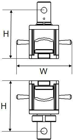
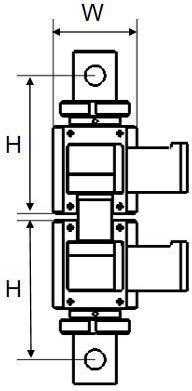
| Overall Height (H) |
Upper Grip: 5.6 in (143 mm)
Lower Grip: 5.9 in (149 mm) |
| Grip Width (W) |
6.5 in (165 mm) |
| Connection Type |
Upper Grip: Ø18 mm pin
Lower Grip: Ø18 mm pin |
| Thread Specification |
M5, M6, M8, M8×1, M10, M10×1.25, M12×1, M12×1.25, M14, M14×1.5, M18, M18×1.5 |
| Minimum Bolt Length |
L ≥ 2.5d |
Thread bushings match internal thread sizes and are inserted into the grip body to ensure proper specimen alignment and load distribution during testing.
Table 2. Optional Thread Bushings - NGA105A Grip
| No. |
Specification |
A (mm) |
B (mm) |
C (mm) |
| NGA105A-27 |
M5 |
27 |
53 |
32 |
| NGA105A-14 |
M6 |
27 |
53 |
32 |
| NGA105A-09 |
M8 |
27 |
53 |
32 |
| NGA105A-26 |
M8×1.0 |
27 |
53 |
32 |
| NGA105A-08 |
M10 |
27 |
53 |
32 |
| NGA105A-15 |
M12 |
27 |
53 |
32 |
| NGA105A-17 |
M12×1.0 |
27 |
53 |
32 |
| NGA105A-18 |
M12×1.25 |
27 |
53 |
32 |
| NGA105A-16 |
M14 |
27 |
53 |
32 |
| NGA105A-24 |
M14×1.5 |
27 |
53 |
32 |
| NGA105A-10 |
M18×1.5 |
27 |
53 |
32 |
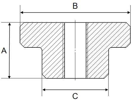 Dimensions A, B and C used in Table 2.
Bolt thimbles serve as sleeves to accommodate bolts of varying outer thread diameters, enabling correct axial alignment and consistent loading during tests.
Table 3. Optional Thread Bushings - NGA105A Grip
| No. |
Specification |
A (mm) |
B (mm) |
C (mm) |
| NGA105A-28 |
M5 |
27 |
53 |
32 |
| NGA105A-19 |
M6 |
27 |
53 |
32 |
| NGA105A-20 |
M8 |
27 |
53 |
32 |
| NGA105A-21 |
M10 |
27 |
53 |
32 |
| NGA105A-22 |
M12 |
27 |
53 |
32 |
| NGA105A-23 |
M14 |
27 |
53 |
32 |
| NGA105A-25 |
M18 |
27 |
53 |
32 |
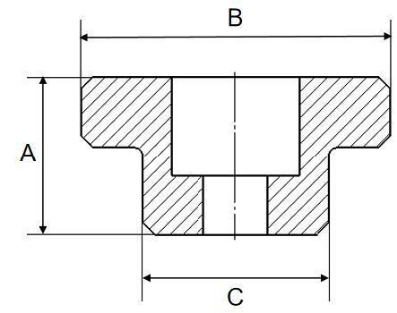 Dimensions A, B and C used in Table 3.
When the fastener is larger or the break load runs past the capacity of the NGA105A, the second grip takes over. It uses a heavier body and a larger pin, and its accessory sets are listed separately below.
Model NGA305C
Bolt and Nut Tensile Grip
The NGA305C Bolt and Nut Tensile Grip is built for high-force tensile testing of bolts and nuts in compliance with GB/T 3098.1-2010 and GB/T 3098.2-2015 standards. With a rated load capacity of 300 kN and compatibility with many metric thread sizes from M3 to M22, this system is suited to advanced testing environments. The grip operates under ambient conditions and features Ø28 mm pin connections for easy integration with universal testing machines. It accommodates bolts with a minimum length of 2.5 times their nominal diameter.
Table 4. NGA305C Bolt and Nut Tensile Grip
| Parameter |
Specification |
| Application |
Tension test for bolts and nuts |
| Maximum Force Capacity |
300 kN |
| Grip Weight |
Upper Grip: 25.6 lbs (11.6 kg)
Lower Grip: 25.6 lbs (11.6 kg) |
| Working Temperature |
Ambient |
| Standard |
GB/T 3098.1-2010GB/T 3098.2-2015 |
| Overall Height (H) |
Upper Grip: 7.8 in (197 mm)
Lower Grip: 7.8 in (197 mm) |
| Grip Width (W) |
4.6 in (118 mm) |
| Connection Type |
Upper Grip: Ø28 mm pin
Lower Grip: Ø28 mm pin |
| Thread Specification |
M3, M4, M5, M6, M8, M8×1, M10, M10×1,M10×1.25, M12, M12×1.25, M12×1.5, M14, M14×1.5,M16, M16×1.5, M18, M18×1.5, M20, M20×1.5, M22 |
| Minimum Bolt Length |
L ≥ 2.5d |
These optional thread bushings allow precise fitment for many bolt sizes and threads. Manufactured to high tolerances, each bushing ensures proper centering and alignment under test load.
Table 5. Optional Thread Bushings - NGA305C Grip
| No. |
Specification |
A (mm) |
B (mm) |
C (mm) |
| NGA305C-07-01 |
M3 |
80 |
78 |
74 |
| NGA305C-07-02 |
M4 |
80 |
78 |
72 |
| NGA305C-07-03 |
M5 |
80 |
78 |
70 |
| NGA305C-07-04 |
M6 |
80 |
78 |
68 |
| NGA305C-07-05 |
M8×1 |
80 |
78 |
64 |
| NGA305C-07-06 |
M8 |
80 |
78 |
64 |
| NGA305C-07-07 |
M10×1 |
80 |
78 |
60 |
| NGA305C-07-08 |
M10×1.25 |
80 |
78 |
60 |
| NGA305C-07-09 |
M10 |
80 |
78 |
60 |
| NGA305C-07-10 |
M12×1.25 |
80 |
78 |
58 |
| NGA305C-07-11 |
M12×1.5 |
80 |
78 |
56 |
| NGA305C-07-12 |
M12 |
80 |
78 |
56 |
| NGA305C-07-13 |
M14×1.5 |
80 |
78 |
52 |
| NGA305C-07-14 |
M14 |
80 |
78 |
52 |
| NGA305C-07-15 |
M16×1.5 |
80 |
78 |
48 |
| NGA305C-07-16 |
M16 |
80 |
78 |
48 |
| NGA305C-07-17 |
M18×1.5 |
80 |
78 |
44 |
| NGA305C-07-18 |
M18 |
80 |
78 |
44 |
| NGA305C-07-19 |
M20×1.5 |
80 |
78 |
40 |
| NGA305C-07-20 |
M20 |
80 |
78 |
40 |
| NGA305C-07-21 |
M22×1.5 |
80 |
78 |
36 |
| NGA305C-07-22 |
M22 |
80 |
78 |
36 |
| NGA305C-07-23 |
M24×2 |
80 |
78 |
32 |
| NGA305C-07-24 |
M24 |
80 |
78 |
32 |
These compact bushings offer reduced height and are suited to applications requiring space savings.
Table 6. Optional Thread Bushings - NGA305C Grip (Compact/Short Type)
| No. |
Specification |
A (mm) |
B (mm) |
C (mm) |
| WLA305C-06-01 |
M3 |
22 |
78 |
3.5 |
| WLA305C-06-02 |
M4 |
22 |
78 |
4.5 |
| WLA305C-06-03 |
M5 |
22 |
78 |
5.5 |
| WLA305C-06-04 |
M6 |
22 |
78 |
6.6 |
| WLA305C-06-05 |
M8 |
22 |
78 |
9 |
| NGA305C-06-06 |
M10 |
22 |
78 |
11 |
| NGA305C-06-07 |
M12 |
22 |
78 |
13.5 |
| NGA305C-06-08 |
M14 |
22 |
78 |
15.5 |
| NGA305C-06-09 |
M16 |
22 |
78 |
17.5 |
| NGA305C-06-10 |
M18 |
22 |
78 |
20 |
| NGA305C-06-11 |
M20 |
22 |
78 |
22 |
| NGA305C-06-12 |
M22 |
22 |
78 |
24 |
| NGA305C-06-13 |
M24 |
22 |
78 |
26 |
The optional wedges provide optimal centering and load distribution for specific thread sizes. Each wedge is available in multiple entry angles (4°, 6°, 10°) to suit different test configurations. Manufactured from high-strength materials, these wedges enhance grip performance and prevent slippage during high-force tensile tests.
Table 7. Optional Wedges - NGA305C Grip
| No. |
Specification |
A (mm) |
B (mm) |
C (°) |
| NGA305C-08-01 |
M3 - 4° |
4 |
7 |
4 |
| NGA305C-08-02 |
M3 - 6° |
4 |
7 |
6 |
| NGA305C-08-03 |
M3 - 10° |
4 |
7 |
10 |
| NGA305C-08-04 |
M4 - 4° |
5 |
9 |
4 |
| NGA305C-08-05 |
M4 - 6° |
5 |
9 |
6 |
| NGA305C-08-06 |
M4 - 10° |
5 |
9 |
10 |
| NGA305C-08-07 |
M5 - 4° |
6 |
10 |
4 |
| NGA305C-08-08 |
M5 - 6° |
6 |
10 |
6 |
| NGA305C-08-09 |
M5 - 10° |
6 |
10 |
10 |
| NGA305C-08-10 |
M6 - 4° |
7 |
12 |
4 |
| NGA305C-08-11 |
M6 - 6° |
7 |
12 |
6 |
| NGA305C-08-12 |
M6 - 10° |
7 |
12 |
10 |
| NGA305C-08-13 |
M8 - 4° |
8 |
16 |
4 |
| NGA305C-08-14 |
M8 - 6° |
8 |
16 |
6 |
| NGA305C-08-15 |
M8 - 10° |
8 |
16 |
10 |
| NGA305C-08-16 |
M10 - 4° |
10 |
20 |
4 |
| NGA305C-08-17 |
M10 - 6° |
10 |
20 |
6 |
| NGA305C-08-18 |
M10 - 10° |
10 |
20 |
10 |
| NGA305C-08-19 |
M12 - 4° |
11 |
24 |
4 |
| NGA305C-08-20 |
M12 - 6° |
11 |
24 |
6 |
| NGA305C-08-21 |
M12 - 10° |
11 |
24 |
10 |
| NGA305C-08-22 |
M14 - 4° |
12 |
28 |
4 |
| NGA305C-08-23 |
M14 - 6° |
12 |
28 |
6 |
| NGA305C-08-24 |
M14 - 10° |
12 |
28 |
10 |
| NGA305C-08-25 |
M16 - 4° |
13 |
30 |
4 |
| NGA305C-08-26 |
M16 - 6° |
13 |
30 |
6 |
| NGA305C-08-27 |
M16 - 10° |
13 |
30 |
10 |
| NGA305C-08-28 |
M18 - 4° |
15 |
34 |
4 |
| NGA305C-08-29 |
M18 - 6° |
15 |
34 |
6 |
| NGA305C-08-30 |
M18 - 10° |
15 |
34 |
10 |
| NGA305C-08-31 |
M20 - 4° |
16 |
37 |
4 |
| NGA305C-08-32 |
M20 - 6° |
16 |
37 |
6 |
| NGA305C-08-33 |
M20 - 10° |
16 |
37 |
10 |
| NGA305C-08-34 |
M22 - 4° |
17 |
42 |
4 |
| NGA305C-08-35 |
M22 - 6° |
17 |
42 |
6 |
| NGA305C-08-36 |
M22 - 10° |
17 |
42 |
10 |
| NGA305C-08-37 |
M24 - 4° |
18 |
44 |
4 |
| NGA305C-08-38 |
M24 - 6° |
18 |
44 |
6 |
| NGA305C-08-39 |
M24 - 10° |
18 |
44 |
10 |
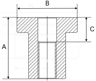
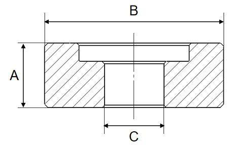 Dimensions A, B and C used in Table 7.
Mandrels are used for clamping bolt samples during tensile testing. These optional accessories match many thread sizes and ensure firm, axial alignment inside the fixture. The NGA305C mandrels are available for metric and fine threads ranging from M3 to M24×2.
Table 8. Optional Mandrels - NGA305C Grip
| No. |
Specification |
A (mm) |
B (mm) |
C (mm) |
| NGA305C-09-01 |
M3 |
77 |
M16 |
10 |
| NGA305C-09-02 |
M4 |
77 |
M16 |
10 |
| NGA305C-09-03 |
M5 |
77 |
M16 |
16 |
| NGA305C-09-04 |
M6 |
77 |
M16 |
16 |
| NGA305C-09-05 |
M8×1 |
77 |
M16 |
20 |
| NGA305C-09-06 |
M8 |
77 |
M16 |
20 |
| NGA305C-09-07 |
M10×1 |
77 |
M16 |
25 |
| NGA305C-09-08 |
M10×1.25 |
77 |
M16 |
25 |
| NGA305C-09-09 |
M10 |
77 |
M16 |
25 |
| NGA305C-09-10 |
M12×1.25 |
77 |
M16 |
30 |
| NGA305C-09-11 |
M12×1.5 |
77 |
M16 |
30 |
| NGA305C-09-12 |
M12 |
77 |
M16 |
30 |
| NGA305C-10-01 |
M14×1.5 |
115 |
M24 |
35 |
| NGA305C-10-02 |
M14 |
115 |
M24 |
35 |
| NGA305C-10-03 |
M16×1.5 |
115 |
M24 |
35 |
| NGA305C-10-04 |
M16 |
115 |
M24 |
35 |
| NGA305C-10-05 |
M18×1.5 |
115 |
M24 |
40 |
| NGA305C-10-06 |
M18 |
115 |
M24 |
40 |
| NGA305C-11-01 |
M20×1.5 |
180 |
M30 |
45 |
| NGA305C-11-02 |
M20 |
180 |
M30 |
45 |
| NGA305C-11-03 |
M22×1.5 |
180 |
M30 |
45 |
| NGA305C-11-04 |
M22 |
180 |
M30 |
45 |
| NGA305C-11-05 |
M24×2 |
180 |
M30 |
45 |
| NGA305C-11-06 |
M24 |
180 |
M30 |
45 |
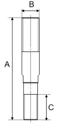
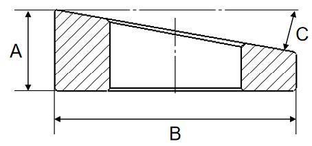 Dimensions A, B and C used in Table 8.
NextGen’s bolt and nut tensile grips deliver consistent, accurate, and standard-compliant testing results. Whether you are validating mechanical properties of fasteners for R&D or certifying production batches, these grips integrate with NextGen’s universal testing machines. Contact us today to discuss configuration compatibility and order the right tensile grip set for your application.
For Laboratories
Need Additional Quality Control Equipment to Build Your Laboratory?
Gripping and fixturing is only one part of a complete quality control laboratory. NextGen can help you equip your entire lab with impact testers, notching and broaching systems, cooling chambers, tensile testers, hardness testers, specimen preparation equipment, and other supporting solutions, all coordinated as one complete project.
- One partner to equip your complete laboratory
- Installation, training, calibration
- Support for the life of the equipment