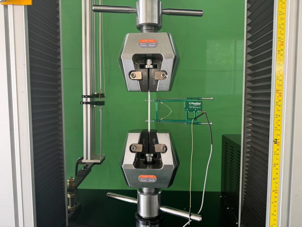
Elongation is the one tensile property that is not measured during the test. Force and extension are captured while the machine is pulling, but elongation after fracture is worked out afterwards, on a bench, from two pieces of broken metal and a pair of marks that somebody applied before the test started. Everything that was careless about those marks arrives, unchanged, in the final report.
That makes gauge marking a measurement step rather than a preparation chore. It is also the step most likely to be done differently by two operators in the same laboratory, on the same shift, using the same standard.
The Marks Are Part of the Measurement Chain
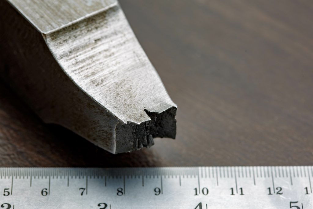
After the specimen breaks, the two halves are fitted back together and the distance between the gauge marks is compared with the original gauge length. The difference, expressed as a percentage, is the elongation that goes on the certificate. Nothing in that sequence re-measures the original spacing: it is taken as known, because it was set before the test.
So an error in the original spacing cannot be detected later. If the marks were unevenly applied, the reported elongation is wrong by an amount nobody can recover, and the test looks perfectly normal from every other angle. A machine that pulled correctly, a load cell within calibration and a clean fracture will all sit in the record alongside a number that was corrupted before the crosshead moved.
Readability matters for the same reason. A mark that was faint to begin with becomes harder to find on a deformed, necked, possibly oxidised surface, and the person measuring after fracture is working with a rule or a caliper against a specimen that no longer has a straight edge. Marks that were consistent and clearly visible make that job mechanical. Marks that were not turn it into an interpretation.
Gauge Length Is Not a Free Choice
Before anything is marked, the gauge length itself has to come from the standard being reported against, and the two dominant standards do not define it the same way.
Proportional Gauge Lengths Under ISO
ISO 6892-1 works from a proportional gauge length, L0 equal to 5.65 times the square root of the original cross-sectional area. For a round solid section that resolves to five diameters, which is why proportional specimens from different stock sizes give results that can be compared at all. The standard is explicit that elongation values are only comparable when the gauge length, the specimen shape and the cross-sectional area are the same, or when the proportionality coefficient is the same. Elongation is a property of a specimen geometry as much as of a material.
Fixed and Proportional Lengths Under ASTM
ASTM E8/E8M is more often used with fixed gauge lengths tied to specimen types, and it permits four diameters for round specimens under half an inch. Product standards add their own requirements on top: ASTM A370, which governs much of the steel product testing that rebar and bar stock fall under, points back to the product specification for what has to be reported.
The practical consequence is that a laboratory testing to both standards is marking to more than one rule, on parts that look similar on the bench. That is precisely the condition in which a hand punch and a steel rule produce quiet inconsistency, because the operator is carrying the difference in their head.
Why the Certificate Says A80 and Not Just Elongation
The subscript on an elongation result is not decoration. Percentage elongation after fracture is the permanent elongation of the gauge length after the break, the difference between the final length and the original one, expressed as a percentage of the original. Written out, it is the final length minus the original length, divided by the original length, times one hundred. Every term in that expression depends on where the marks were.
Where the gauge length is proportional to the cross-section, the result is reported as A. Where it is a fixed length instead, the length is carried in the name, so a result taken over 80 mm is reported as A80mm. That convention exists because the number alone is not transferable: a material tested over a proportional length and the same material tested over a fixed 80 mm length will not give the same percentage, and neither result is wrong. They are answers to two different questions.
This is the point where marking discipline turns into commercial risk. A certificate that reports elongation without making the gauge length explicit invites a customer to compare it against a value obtained a different way, and the disagreement that follows is not resolvable from the paperwork. The marks, the gauge length and the designation travel together or the number stops meaning anything.
Where the Break Falls Changes What You Are Allowed to Report
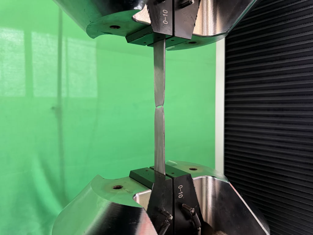
A tensile specimen does not break in the middle because the engineer would prefer it to. Both ASTM E8/E8M and ISO 6892-1 place limits on where the fracture may sit relative to the gauge marks, because a break close to one of them means the necking region is no longer centred in the length being measured, and the elongation calculated from it is not representative of the material.
This is where marking pitch stops being a detail. When the marks are spaced at a known, even interval along the whole reduced section rather than only at the two ends of the gauge length, an off-centre break can still be handled: the intervals are counted and the measurement is shifted so that the same total length is assessed with the fracture properly placed within it. With two marks and nothing between them, there is nothing to count, and a specimen that broke in the wrong place is simply scrapped.
For a laboratory testing rebar in volume, that difference is measured in re-tests, in material, and in the hours it takes to machine or cut a replacement. Even spacing along the specimen is cheap insurance against a fracture position nobody controls.
What an Automatic Marker Actually Changes
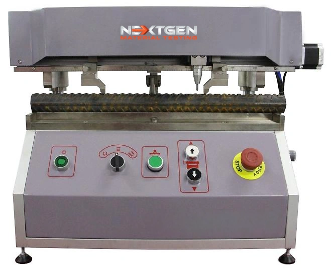
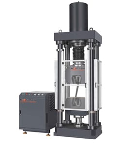
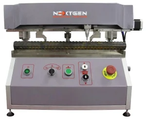
The GenMark 500 exists to take the variation out of this step. A pneumatic marking needle runs along a lead screw driven by a servo motor, so the pitch is set by the machine rather than by hand, and switches between 5 mm and 10 mm without the specimen being repositioned. Gauge length accuracy is held to the greater of 0.05 mm or 0.5 percent across a marking range that runs to 500 mm.
Two design choices matter more than they first appear. The marking force is set by regulating air pressure instead of by changing tooling, which means the same needle can mark soft and hard material at a depth appropriate to each. A mark pressed too hard into a specimen is not neutral: it is a surface defect in the reduced section, and it can influence where the specimen decides to break. Controlling that force is controlling a variable that hand marking leaves to how tired the operator is.
The second is service life. The needle is tungsten steel at HRC 60 to 65 and is quoted at around 150,000 markings before regrinding or replacement, with the needle and its pneumatic assembly built as a single unit so a change does not require realignment. A marking tool that drifts as it wears reintroduces exactly the inconsistency the machine was bought to remove, so the wear behaviour of the needle is part of the measurement argument rather than a maintenance footnote.
Specimen handling is deliberately broad, because the same bench usually sees more than one product form. The machine takes round sections from 4 mm to 50 mm in diameter and flat sections from 15 mm to 60 mm wide and up to 50 mm thick, with a press block that adjusts for length and a fixture that moves to suit round or flat stock. It is a bench unit of 850 by 350 by 460 mm and 50 kg, runs on standard single phase power and shop air between 0.4 and 0.7 MPa, and is declared to ISO 6892-1 and ASTM E8/E8M.
None of that makes a tensile result correct on its own. It removes one specific source of error, the one that is invisible after the fact, and it makes the preparation step reproducible enough that an auditor reviewing how specimens were prepared gets a procedure rather than an anecdote.
Keep Reading in Universal Testing Machines for Metal Testing
See the Universal Testing Machines for Metal Testing range Flexural (Bend) Testing Explained: 3-Point vs 4-Point, Standards, and SetupFlexural (bend) testing explained: what it measures, three-point vs four-point setups, the standards for plastics, metals, composites and concrete, and how to choose the right fixtures and...Read the articleGenTest Software Setup Guide for NextGen NG-EML Universal Testing MachinesGenTest setup affects the full UTM testing workflow: method storage, PC-to-controller communication, user permissions, simulation files, live data acquisition, and report output. This guide follows the GenTest setup video step by step for NextGen NG-EML electromechanical universal testing machines. It covers installation, license activation, workspace configuration, UTM controller connection, safety and peripheral setup, user management, DEMO Mode, simulation files, Control Panel setup, Quick Test, and test method creation. GenTest is the software layer where the test method, machine connection, operator input, live data, calculated results, and report output come together. For operators, service teams, QA/QC labs, and R&D users, the goal is to...Read the articleMeet NG-AutoPol – Automatic Longitudinal Polisher for Tensile SpecimensHaving trouble achieving consistent surface finishes on your tensile or fatigue specimens? Even the most precise machining can leave subtle marks and residual stresses that influence test results. When every micron matters, surface preparation becomes more than just a step — it defines the reliability of your data. That’s where NG-AutoPol comes in. This automatic longitudinal polisher system brings precision, repeatability, and ease of use into one complete solution. Designed for both cylindrical and flat tensile specimens, it minimizes residual stress and provides a uniform finish for accurate tensile and fatigue testing. In this article, we’ll take you through everything you need to know about the NG-AutoPol — what longitudinal polishing systems...Read the articleThe Rockwell Scale Explained: How to Choose Between HRC, HRB and Superficial ScalesA Rockwell hardness number tells you very little until you know the letters that come with it. A reading of 60 on one scale and a reading of 60 on another describe different materials, tested with a different indenter under a different force, and neither can be compared with the other until someone knows which scale produced it. A drawing that asks for 60 HRC is specifying a whole test: a diamond indenter, a total force of 150 kgf and a depth measurement made in a defined way. ASTM defines thirty Rockwell scales. Picking the right one is a decision that can go wrong without any warning, because the wrong scale does not produce an error message. It produces a number, and that number looks just as plausible as a valid one. This article explains what...Read the articleHow to Measure Case Depth: Effective Depth, Total Depth and the Hardness Limit That Decides ItA drawing asks for case depth in a single number, and that number carries a tolerance, an acceptance decision and sometimes a rejected heat lot. What the drawing rarely says is which of two different depths it means, or which hardness value marks the boundary. Two laboratories can follow the same procedure on the same part, measure carefully, and report depths that differ by a noticeable margin, because they drew the line in different places. The measurement itself is not the hard part. Agreeing on what is being measured is. This article is about the traverse: how case depth is defined, what fixes the boundary, and what the work demands from the equipment that produces it. If you are still deciding whether microhardness is the right method at all,...Read the articleVicat Testing and What Cement Setting Time Really Tells YouVicat setting time is a standardized cement paste measurement used for specification compliance and quality control. It identifies when a paste prepared under defined conditions reaches the initial and final set criteria of the selected method. It does not directly predict concrete haul time, cold joint formation, finishing time or field workability, because those depend on the complete mixture: water content, admixtures, aggregates and temperature. This guide covers what Vicat setting time measures, how the apparatus produces the number, which test conditions make results drift, and what separates a manual instrument from an automatic one. Setting Time Is Not Early Strength Initial and final set describe the stiffening of a standardized cement...Read the articleBrinell, Rockwell, Vickers, or Microhardness: Which Test Makes Sense for Your Application?Choosing a hardness test starts with the part itself. Material type, section thickness, geometry, surface condition, inspection purpose, and required testing speed all affect which method will produce a reliable result. Brinell, Rockwell, Vickers, and microhardness methods work differently, so they are not equally suitable for the same component or the same quality task. Brinell, Vickers, and Knoop are based on the size of an indentation, while Rockwell is based on indentation depth. That difference directly affects how the result is obtained and where the method fits best. In production and lab work, problems usually appear when the test method does not fit the application. A part may be too thin for the selected load, the surface may be too rough...Read the articleSpecimen Size Effects in Charpy Testing: What Engineers Need to KnowCharpy V-notch testing remains widely used because it offers a standardized and efficient way to evaluate impact behavior in metallic materials. In production, qualification, and failure analysis work, it is often used to compare toughness response across temperatures, material conditions, and product forms. The standard Charpy specimen measures 10 × 10 × 55 mm, but that geometry is not always available in practice. Thin sections, weld zones, heat-affected zones, and limited extraction volumes often make full-size specimens impractical. ISO 148-1 addresses this directly by permitting sub-size specimens when a standard specimen cannot be produced, including reduced-thickness options such as 7.5 mm, 5 mm, and 2.5 mm. That change affects more than the...Read the article
Machines Behind This Article
 Universal Testing Machines for Metal TestingGenMark 500 – Automatic Gauge Length Marking MachineThe GenMark 500 is a full-automatic gauge length marking machine for metal bar, rebar and wire rod, applying the reference marks used to determine elongation after...View productServoNG-SHM Class D – Servo-Hydraulic Universal Testing MachineNG-SHM Class D is a servo-hydraulic universal testing machine for high-force mechanical testing of metals and structural components. Available in 600 kN, 1000 kN,...View product
 Electromechanical Universal Testing Machines for Rubber TestingNG-EML Series A – Single-Column Universal Testing Machine (50 N – 5 kN)NG-EML Series A is a compact single-column benchtop universal testing machine for low-force tensile, compression, and flexural testing. Covering 50 N to 5 kN...View product
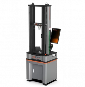 Electromechanical Universal Testing Machines for Rubber TestingNG-EML Series B – Dual-Column Universal Testing Machine (100 N – 10 kN)NG-EML Series B is a dual-column benchtop electromechanical universal testing machine for precision testing from 100 N to 10 kN. Built for research and industrial...View product
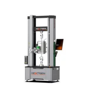 Electromechanical Universal Testing Machines for Rubber TestingNG-EML Series C – Dual-Column Universal Testing Machine (5–50 kN)NG-EML Series C is a dual-column electromechanical universal testing machine available in bench-top and floor-standing formats from 5 kN to 50 kN. Built for...View product
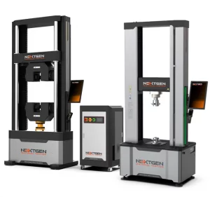 Electromechanical Universal Testing Machines for Rubber TestingNG-EML Series D – Floor-Standing Universal Testing Machine (50–1000 kN)NG-EML Series D is a heavy-duty floor-standing electromechanical universal testing machine for high-capacity tensile, compression, and flexural testing. Available...View product
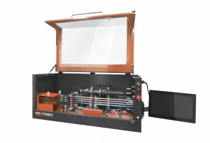 Tensile Sample PreparationNG-AutoPol – Automatic Longitudinal Polisher for Tensile SpecimensNG-AutoPol is an automatic longitudinal polishing system for metallic tensile and fatigue specimens. It removes machining marks, grinding stress, and residual...View product
 Tensile Sample PreparationTensileMill CNC MICRO – Flat Tensile Specimen Preparation MachineTensileMill CNC MICRO is a compact 2-axis machine for preparing flat tensile and impact specimens in-house. Designed for metals, plastics, and composites, it...View product