Most engineers meet tensile testing first, then hardness, then impact. Bending tends to get learned later, often the day a plastic bracket cracks in service or a formed part fails a check. Flexural testing uses a supported-beam setup to measure how a material behaves when it is loaded across a span rather than pulled end to end, and it is one of the everyday tests run on a universal testing machine.
It is worth being precise about the name. Flexural testing is related to, but not the same as, the ductility and guided-bend tests used to check formed metal and welded joints. Those bend a sample to an angle and look at whether it cracks, while flexural property testing measures numbers such as flexural strength, stiffness, and strain. This guide is mainly about flexural property testing, and it flags where the bend-for-ductility methods and their standards differ, because mixing the two is where most confusion starts.
The material below covers what the test measures, how three-point and four-point setups differ, the formulas and what each symbol means, the standards that apply by material, the setup details that decide whether your data holds up, and how to match a frame and fixture to the job. It is written for QC engineers, lab managers, and R&D teams who need results they can defend in an audit.
What Flexural Testing Measures
In a flexural test the specimen rests on two supports while a load is applied from above, bending it until it either breaks or reaches a set deflection. The top surface goes into compression, the bottom into tension, and a neutral plane in the middle sees almost no stress. Because the outer fibers carry the highest stress, bending is sensitive to surface condition, coatings, and near-surface defects, which is part of why it is a useful check. From a single test you typically read three things:
- Flexural strength: the maximum stress the outer fiber reaches before failure. For brittle materials this is the fracture point, and for concrete it is reported as the modulus of rupture.
- Flexural modulus: the stiffness in bending, taken from the slope of the early, straight part of the load and deflection curve, which tells you how much a part deflects under a given load.
- Behavior under load: whether the material yields and keeps bending or fails abruptly, which shapes how the result is interpreted.
Why It Matters, and Who Relies on It
Many components see bending, combined loading, or local flexure in service rather than ideal uniaxial tension, so a bending test can reveal surface-sensitive or geometry-dependent behavior that a tensile test does not show. When the specimen geometry and loading mode are relevant to the application, a flexural result can track bending-related service behavior more closely than tension alone. The test is also efficient in a lab: many standardized methods use rectangular bars or beams that are quick to prepare, and most flexural setups need no gripping, which removes a common error source and avoids crushing brittle or coated samples.
That combination of relevance and speed is why flexural and bend testing turns up across a wide range of labs:
- Plastics and composites labs qualify resins, laminates, and molded parts to methods such as ASTM D790, ASTM D6272, and ISO 178.
- Metal and welding shops run ductility and guided-bend tests to confirm a formed part or a weld procedure will not crack.
- Concrete and construction labs report modulus of rupture for pavements, beams, and fiber-reinforced mixes.
- Ceramics and electronics makers measure the strength of brittle substrates, tiles, and technical ceramics.
- Wood and building-product labs grade lumber and panels for stiffness and strength.
Three-Point vs Four-Point Bending
The two standard setups differ in how the load is applied, and that changes where the specimen is most stressed. It is the first choice to settle in a bend test, because it drives both the fixture you need and how the result should be read. The diagram below shows the bending moment along the specimen for each case.
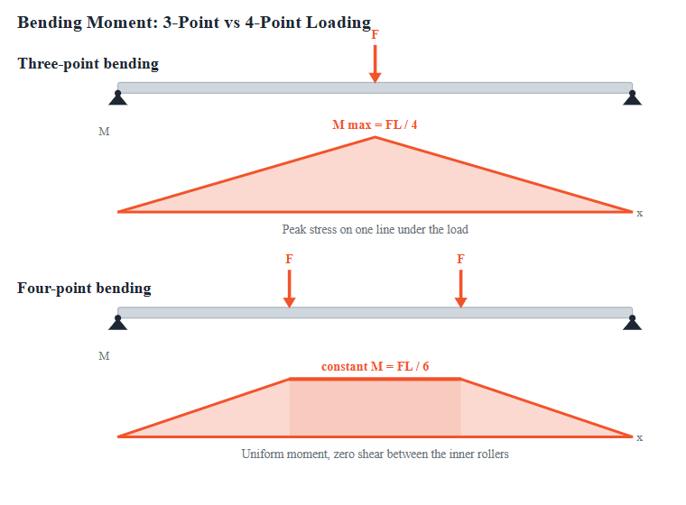
In three-point bending a single roller presses at the center of the span, so the bending moment peaks on the line directly under that roller and falls off toward the supports. The setup is simple, uses less material, and is the default in many plastics methods. Its limitation is that the highest stress sits in one narrow region, so the result leans on whatever happens to be there.
In four-point bending two rollers press at set positions inside the supports. Between those inner rollers the bending moment is constant and the shear is zero, which creates a region of pure bending and exposes a length of the specimen to the maximum stress rather than a single line. That raises the chance a critical defect influences the result, which is why four-point is common for composites, ceramics, and research work. The trade-offs line up as follows.
| Factor | Three-point | Four-point |
|---|---|---|
| Stress distribution | Maximum moment on the line under the central roller | Constant maximum moment between the two inner rollers |
| Flaw sensitivity | Most sensitive to defects near the central high-stress region | Exposes a larger length to the peak moment, raising the chance a critical defect affects the result |
| Material and setup | Simpler, less material, faster | More tooling and alignment care |
| Common use | Routine plastics QC | Composites, ceramics, research, concrete beams |
Calculating Flexural Strength and Modulus
 Flexural results come from the force, the span, and the specimen cross section. The equations below apply to a rectangular, simply supported specimen under the stated loading geometry. In them, F is the total force recorded by the testing machine, which in the four-point cases is the total force and not the force at each loading nose. L is the outer support span, b and d are the specimen width and depth, D is the mid-span deflection, and m is the slope of the load and deflection curve.
- Three-point flexural stress: σf = 3FL / (2bd²)
- Three-point flexural strain: εf = 6Dd / L²
- Three-point flexural modulus: Ef = L³m / (4bd³)
- Four-point stress, third-point loading: σf = FL / (bd²)
- Four-point stress, quarter-point loading: σf = 3FL / (4bd²)
Use the applicable standard for the specimen size, span, loading-nose positions, how deflection is measured, and any compliance or large-deflection correction, since these are not universal. ASTM D790 and ISO 178 differ on this point: ISO 178 calls for direct deflection measurement or a compliance correction, while ASTM D790 allows crosshead displacement under defined conditions. One practical note on the numbers themselves: depth is squared or cubed in these equations, so a small error in the measured thickness produces a much larger error in the reported strength or modulus. Measure width and thickness at several points and use the correct value.
Reading the Curve: Brittle vs Ductile
The shape of the load and deflection curve carries as much information as the peak number, because two materials can reach a similar flexural strength and get there very differently. The curves below show the two ends of that range.

A brittle material such as a technical ceramic, a cured thermoset, or a fiber composite rises almost in a straight line and then fractures, so the flexural strength is the fracture point with little warning. These materials reward careful roller contact and good alignment, since a stress concentration at a contact point can trigger an early, misleading break. A ductile material such as many metals and some thermoplastics rises, reaches a yield point, and keeps bending. For these, a flexural test may report the load at a set deflection, while whether the material cracks after being bent to a required angle is judged by a separate ductility bend test to ASTM E290 or ISO 7438. Welded joints are qualified with weld-specific methods such as ASTM E190 or ISO 5173 rather than the general bend standards.
Standards by Material Family
Flexural and bend testing is governed by material-specific standards, and the method fixes the setup, span, specimen size, and reported values, so the standard is what drives the fixture choice. The table below maps the most requested standards to the materials they cover. Always confirm the current edition, since numbers move and older documents can be withdrawn.
| Material | Key standards | What to know |
|---|---|---|
| Rigid plastics, three-point | ASTM D790 | Results at break, yield, or a 5% outer-fiber strain limit for the method. |
| Rigid plastics, three-point | ISO 178 | Reports flexural stress at 3.5% strain, at yield, maximum, or break by behavior. |
| Rigid plastics, four-point | ASTM D6272 | Two loading noses with a constant-moment region between them. |
| Fiber-reinforced composites | ASTM D7264, ISO 14125 | Three- or four-point; four-point gives a uniform-moment region. |
| Metals, ductility bend | ASTM E290, ISO 7438 | Bend over a mandrel to an angle, then inspect for cracks. ISO 7438 excludes welds; welds use ASTM E190 or ISO 5173. |
| Concrete and mortar | ASTM C78 (third-point), ASTM C293 (center-point), ASTM C1609 | C78 gives modulus of rupture; center-point (C293) generally reads higher, and the two are not interchangeable. |
| Advanced ceramics | ASTM C1161 | Four-point is common; brittle, so contact and alignment are critical. |
| Structural and clear wood | ASTM D198; ISO 13061-3, ISO 13061-4 | D198 for structural-size lumber; ISO 13061-3 and 13061-4 for strength and modulus of small clear specimens. |
A related point that trips people up: ASTM D198 covers flexural and other mechanical tests on structural-size lumber, but mechanical fastener withdrawal is a separate test under ASTM D1761, not part of D198. When a specification lists a standard you do not see here, send it over and we will confirm whether the fixture and frame you are considering can meet it.
Fixtures and Setup: Getting It Right
A bend test is only as good as its fixture, because the supports and loading rollers control where the stress goes, how the specimen contacts the tooling, and whether the result can be repeated. A handful of details do most of the work here, and each of them shows up as scatter in the data when it is wrong.
- Span to depth ratio: set the span from the standard, commonly 16:1 for plastics. Too short a span adds shear and reads high; too long risks deflections that break the small-deflection assumption.
- Roller diameter and contact: rollers that are too sharp create a stress concentration and can cause an early failure, which is why standards specify roller radii, especially for brittle materials.
- Alignment and squareness: loading rollers should sit parallel to the supports and centered on the span, since a twisted or off-center setup adds torsion and skews the reading.
- Specimen measurement: because depth is cubed in the modulus equation, measure width and thickness at several points and use the correct value.
The mistakes that most often ruin bend data follow from those same points: using three-point when the method calls for four-point or the reverse, guessing the span instead of setting it from the specimen depth, running worn or wrong-radius rollers that pinch brittle samples, skipping a calibration check so the force reading drifts, and reading strength off a machine that was never aligned to the fixture axis. None of them are exotic, and all of them are avoidable with a short setup routine.
Choosing NextGen Equipment for Flexural Testing
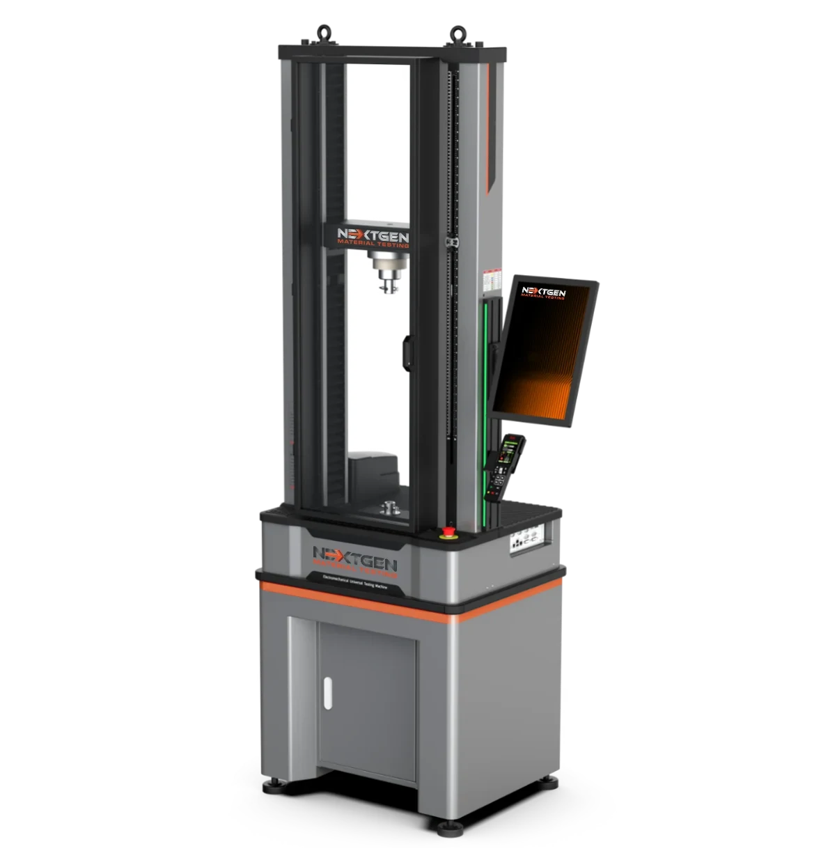 A flexural setup comes down to a load frame, the right bending fixture, and software to run the method and record the curve, and NextGen supplies all three so they are matched from the start. The frame sets the force range: the electromechanical universal testing machines run from single-column benchtop units for light plastics work up to dual-column floor models, while the servo-hydraulic frames handle high-force bending of metals, thick composites, and concrete beams.
One setup detail is worth flagging, because it is easy to get wrong: sizing the frame from the expected breaking force alone can leave you short on resolution. For low-force plastic specimens an oversized load cell may have the capacity but too little resolution in the early slope region used for modulus, so frame capacity and measurement range are best chosen separately rather than from a single force number.
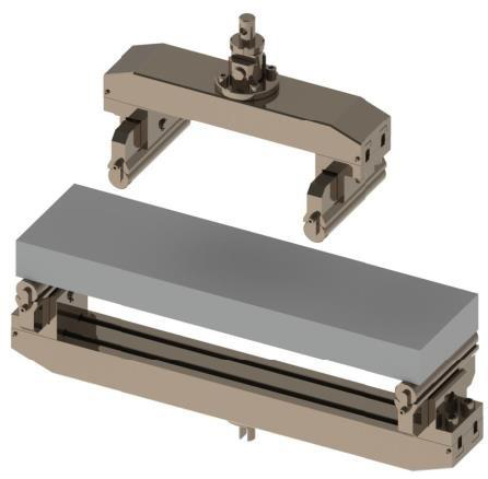
On the tooling side, the bending and flexure fixtures cover the common cases: 3-point and 4-point fixtures for metals, ceramics, composites, and concrete, flexure fixtures for large or brittle specimens, heavy-duty fixtures for hydraulic frames rated to high forces, and wood testing fixtures. Where the job is sheet-metal ductility and formability rather than flexural properties, the NG-FLX Series A is purpose-built for controlled sheet bending, three-point bend, flattening, and formability checks.
Once the standard is known, the table below is a starting point for matching it to a configuration, which you can then refine with the team.
| Application | Typical method | Starting equipment |
|---|---|---|
| Rigid plastics | ASTM D790 or ISO 178 | Lower-force electromechanical UTM with a 3-point fixture |
| Four-point plastics | ASTM D6272 | Electromechanical UTM with an adjustable 4-point fixture |
| Polymer composites | ASTM D7264 or ISO 14125 | UTM with 3-point and 4-point tooling and direct deflection measurement |
| Sheet-metal ductility | ASTM E290 or ISO 7438 | NG-FLX Series A or compatible guided-bend tooling |
| Concrete beams | ASTM C78, C293, or C1609 | High-capacity frame with a standard-specific beam fixture |
| Structural wood | ASTM D198 | Large-span fixture and a floor-standing frame |
Software and calibration close the loop. GenTest data acquisition software runs the flexural method and records the load and deflection curve, with the flexural results calculated in software so they stay consistent between operators. For work under audit, the alignment device supports load-train alignment verification to ASTM E1012 and ISO 23788, which is often part of workflows prepared for aerospace and NADCAP requirements, and NextGen provides calibration traceable to recognized standards. Being NADCAP-ready in this sense refers to the alignment and verification workflow, not an automatic accreditation.
Flexural testing looks simple, and the specimens usually are, but the result depends on the loading geometry, the fixture, and the calibration lining up with the standard. Get those right and you have a fast, repeatable measurement of how a material behaves in bending. To set it up for your material, send us the material, the test standard, your specimen dimensions, and the expected force range, and the team will recommend the load frame, bending fixture, roller geometry, and deflection measurement to match. You can request a quote or contact our team to get started.
Keep Reading in Universal Testing Machines for Metal Testing
See the Universal Testing Machines for Metal Testing rangeMachines Behind This Article
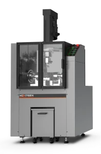 Metal TestingNG-FLX Series A – Flexural and Bend Testing SystemNG-FLX Series A is an electromechanical flexural and bend testing system for controlled sheet metal bending, three-point bend testing, flattening tests, ductility...View product
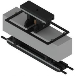 Grips and Fixtures for NextGen Universal Testing Machines (UTMs)Flexure Fixtures for Large and Brittle SpecimensThese flexure fixtures are designed for precise bending tests on large, brittle, or high-strength specimens, including metals, ceramics, composites, concrete, and...View product
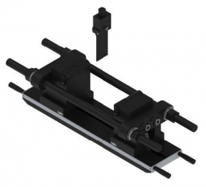 Metal TestingHeavy-Duty Bending Fixtures for Hydraulic Flexural TestingHeavy-duty bending fixtures support high-force flexural testing of metals, composites, ceramics, reinforcing bars, and structural materials on hydraulic universal...View product
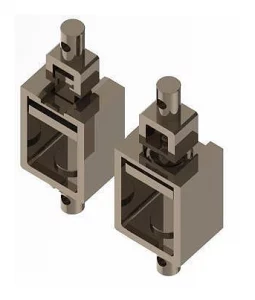 Grips and Fixtures for NextGen Universal Testing Machines (UTMs)Grips and Fixtures for Wood TestingThese wood testing grips and fixtures support tensile, shear, flexural, internal bond, and fastener-related evaluation of engineered wood, panels, boards, and...View product
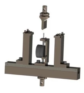 Grips and Fixtures for NextGen Universal Testing Machines (UTMs)3-Point and 4-Point Bending Fixtures for Flexural TestingThese 3-point and 4-point bending fixtures support flexural strength, deformation, and modulus testing of natural stone, ceramics, composites, concrete, metals,...View product
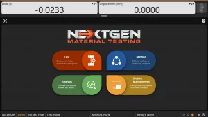 Electromechanical Universal Testing Machines for Rubber TestingGenTest – Advanced UTM Testing SoftwareGenTest is NextGen’s advanced UTM testing software for electromechanical universal testing machines, managing test setup, live control, data acquisition,...View product