A drawing asks for case depth in a single number, and that number carries a tolerance, an acceptance decision and sometimes a rejected heat lot. What the drawing rarely says is which of two different depths it means, or which hardness value marks the boundary. Two laboratories can follow the same procedure on the same part, measure carefully, and report depths that differ by a noticeable margin, because they drew the line in different places. The measurement itself is not the hard part. Agreeing on what is being measured is.
This article is about the traverse: how case depth is defined, what fixes the boundary, and what the work demands from the equipment that produces it. If you are still deciding whether microhardness is the right method at all, that question is answered separately in our guide to choosing a hardness testing method for reliable QC.
Two Depths That Sound Alike and Are Not
Case hardening leaves a gradient, not a layer with an edge. Hardness falls from the surface toward the core over a distance, and where you declare the case to end is a convention rather than a discovery. Two conventions are in common use, and they answer different questions.
Effective case depth, written as case hardening depth or CHD in ISO practice, is the perpendicular distance from the surface to the point where hardness first falls to a stated limiting value. It is a functional depth: it says how far into the part the material still meets a hardness the designer asked for. Total case depth is the metallurgical one, the distance to where the case and the core are no longer distinguishable. The two numbers are not interchangeable, they do not sit in a fixed ratio, and a part can pass on one and fail on the other.
Most acceptance work runs on effective depth, because that is the number tied to a service requirement such as wear resistance or contact fatigue. Total depth tends to appear in process development, failure investigation and disputes about how a furnace cycle actually ran. When a drawing says only “case depth” with a tolerance, the first job is to establish which of the two the customer means, before a single indentation is made.
The Hardness Limit Is a Decision, Not a Constant
Effective depth only exists once somebody names the hardness that defines it. For carburized and carbonitrided steels the common limit is 550 HV, or the equivalent value of 550 HK where Knoop is used instead. Read literally, case hardening depth is the perpendicular distance from the surface to the layer that has a hardness of 550 HV.
That limit is not universal, and the reason it moves is worth understanding. If the core itself is already hard, a 550 HV line can fall in material that was never part of the case, and the reported depth stops meaning anything. Where the steel shows a hardness above 450 HV at a distance of three times the case hardening depth from the surface, the limiting value may be raised, in steps of 25 units, until the boundary again separates case from core. A harder core therefore pushes the limit upward by agreement rather than invalidating the measurement.
The practical consequence is administrative rather than technical. A case depth result is only comparable with another when three things travel with it: which depth was measured, what limiting hardness was used, and at what load. A number reported without them cannot be checked by anyone, including the laboratory that produced it.
The Standard on Your Drawing May No Longer Exist
Case depth callouts age badly. ISO 2639 is still printed on drawings and quality plans across the industry, and it is the document many engineers first learned the subject from. It is also withdrawn.
Its content did not disappear. ISO 18203 cancels and replaces ISO 2639:2002 together with ISO 3754:1976 and ISO 4970:1979, folding three documents that measured surface hardened layers in almost the same way into a single standard. For a laboratory, that means an incoming drawing citing ISO 2639 is a legacy callout, not an error, and the correct response is to confirm with the customer which document governs before quoting a result against it. Purchase specifications frequently lag the standards they reference by years, and a report that silently substitutes one standard for another creates a dispute rather than avoiding one.
Regional adoptions add their own layer, and a customer in one market may recognise a national version of the same method while rejecting the ISO number. This is why edition control belongs in the quality plan rather than in an operator’s memory.
One Standard, Three Depths, Because There Are Three Treatments
Merging three documents into one was not housekeeping. The three older standards existed because a hardened surface can be produced in fundamentally different ways, and each way leaves a gradient that has to be read against a different reference. The consolidated standard keeps all three, which is why the term “case depth” on its own is ambiguous until the treatment is named.
Carburized and carbonitrided parts are measured as case hardening depth against the 550 HV line described above. Parts hardened by heat alone, whether by flame, induction, electron beam or laser, are measured as surface hardening depth, and there the limiting hardness depends on what the component has to do in service, so it is agreed with the customer rather than assumed from a table. Nitrided parts are different again: nitriding hardness depth is referenced to the core, conventionally the core hardness plus 50 HV, which means the same nitriding cycle on two different core conditions legitimately produces two different depths.
That last case is the one that generates arguments. A supplier and a customer can both measure correctly, both report in good faith, and disagree, simply because one anchored the limit to the core it found and the other used a fixed number carried over from a carburizing specification. The treatment determines the convention, and the convention determines the number.
What the Traverse Asks of the Instrument
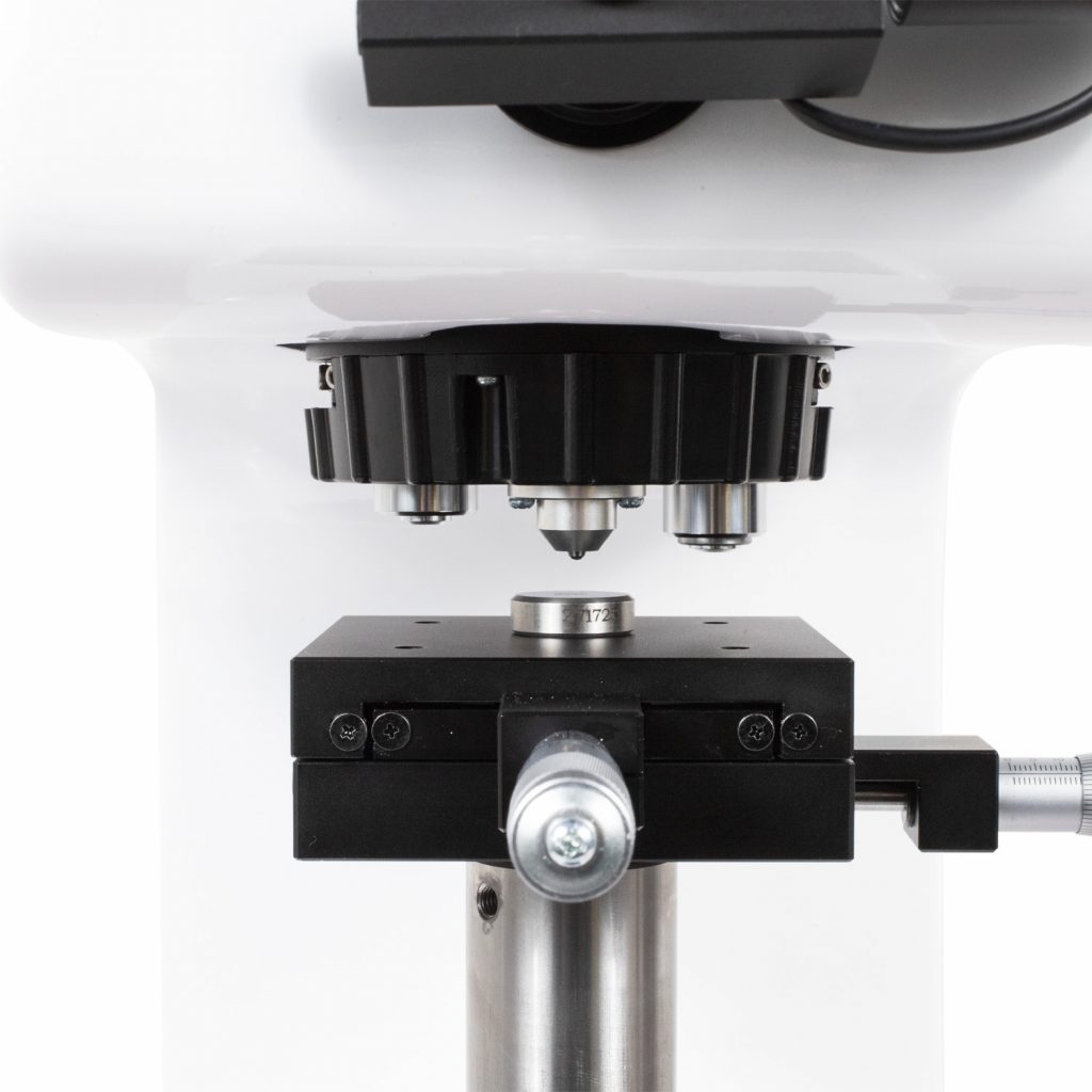
A case depth profile is an unforgiving use of a microhardness tester, and it exposes weaknesses that a single spot check never will. The measurement is optical: a diamond is pressed into a prepared cross-section under a light load, and the hardness follows from the diagonals of the indentation it leaves. Everything that blurs, shifts or drifts between one indentation and the next shows up directly in the depth number.
Load range is the first constraint. Our NG-1000 micro Vickers and Knoop tester works between 10 g and 1 kg, and that span matters because the indentation has to stay small enough to resolve a steep gradient while remaining large enough to measure reliably. A load chosen for convenience near the surface can put neighbouring indentations close enough to interfere with each other, and the profile flattens in exactly the region where it should be steepest.
The choice between the two indenters belongs to the traverse rather than to the laboratory’s habits. A Vickers indentation is symmetrical and is the default for hardness profiles, measured under ISO 6507. A Knoop indentation is elongated, so its long diagonal can be read at a useful size while the short one stays narrow, and indentations can sit closer together along the direction the gradient runs. On a steep case, or on a thin layer where a Vickers impression would run out of room, that geometry is what keeps the profile from being averaged into a straight line. The method for it is ISO 4545, and an instrument that carries both indenters lets the operator pick per job instead of per machine.
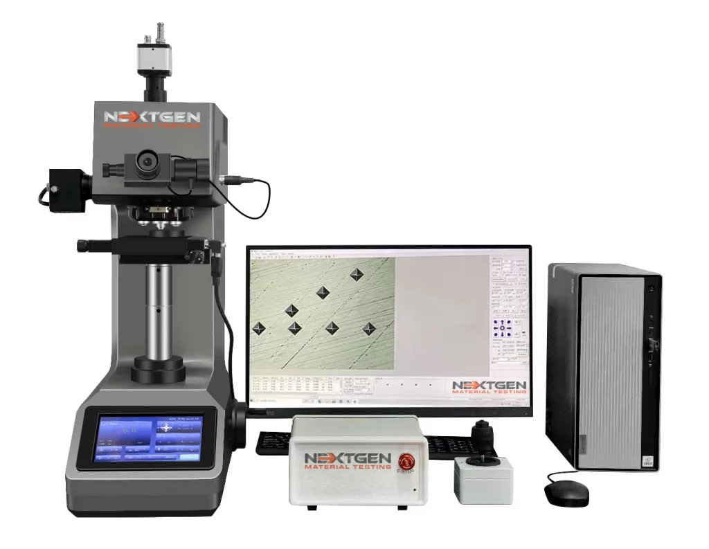
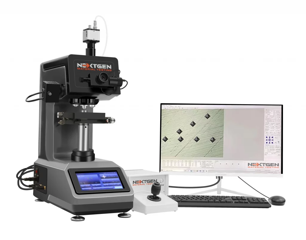
Optics and stage behaviour decide whether the profile repeats. Reading a diagonal is a human judgement unless the system measures it for you, and across a traverse of many indentations that judgement drifts. Positioning has to be equally disciplined, because a depth result is a hardness plotted against a distance, and an uncertain distance corrupts a perfectly good hardness. Repetitive work of this kind is where motorised stages, automated focus and image based measurement earn their place, and where manual instruments quietly lose repeatability between operators.
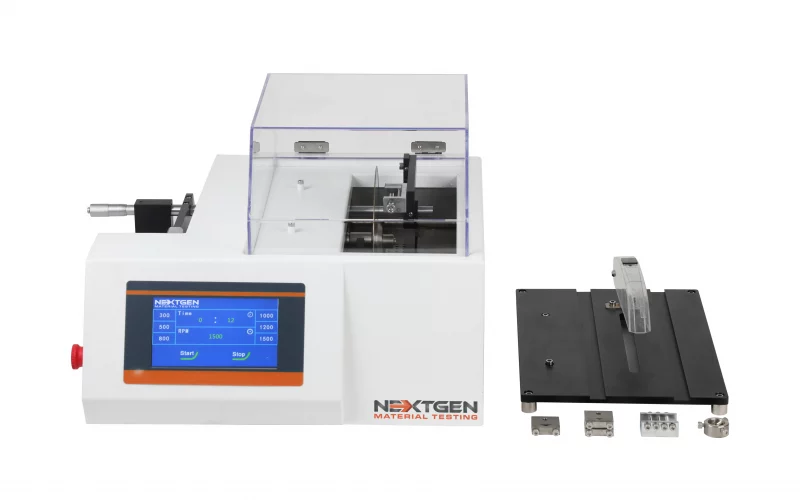
Preparation sits underneath all of it. The cross-section has to be cut without heating the surface, mounted with the edge properly supported, and polished so the first indentation can sit close to the surface without falling into a rounded edge. A specimen that loses its edge during preparation shortens every depth measured on it, and no amount of instrument quality recovers that. Our ASTM E384 page covers the microindentation method these traverses run under.
Reporting a Number That Survives an Audit
The last step is the one that turns a measurement into evidence. A case depth entry that an auditor can follow names the depth type, the limiting hardness, the test load, the standard and edition it was measured to, the instrument, and the verification status of that instrument on the day of the test. Traverses are usually run more than once on a part, because a single line of indentations through a gradient is a small sample of a surface treated component.
Keep Reading in Vickers and Knoop Hardness Testers
See the Vickers and Knoop Hardness Testers range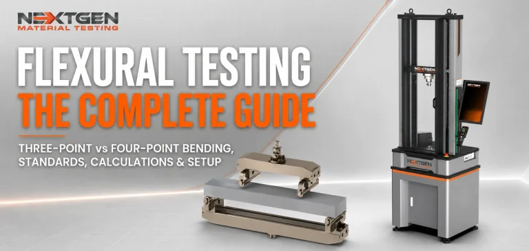 Flexural (Bend) Testing Explained: 3-Point vs 4-Point, Standards, and SetupFlexural (bend) testing explained: what it measures, three-point vs four-point setups, the standards for plastics, metals, composites and concrete, and how to choose the right fixtures and...Read the articleGenTest Software Setup Guide for NextGen NG-EML Universal Testing MachinesGenTest setup affects the full UTM testing workflow: method storage, PC-to-controller communication, user permissions, simulation files, live data acquisition, and report output. This guide follows the GenTest setup video step by step for NextGen NG-EML electromechanical universal testing machines. It covers installation, license activation, workspace configuration, UTM controller connection, safety and peripheral setup, user management, DEMO Mode, simulation files, Control Panel setup, Quick Test, and test method creation. GenTest is the software layer where the test method, machine connection, operator input, live data, calculated results, and report output come together. For operators, service teams, QA/QC labs, and R&D users, the goal is to...Read the article
Machines Behind This Article
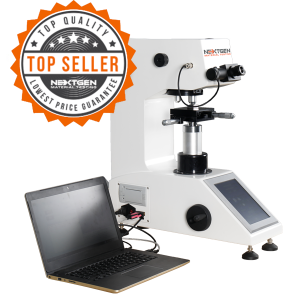 Vickers and Knoop Hardness TestersMicro Vickers and Knoop Hardness TesterThe NG-1000 Micro Vickers and Knoop Hardness Tester is designed for accurate microhardness testing with digital, standard, and CCD optical-analysis configurations....View product
 Precision Metallographic CuttingGenCut GL100E – Low-Speed Precision Metallographic CutterGenCut GL100E is a low-speed automatic precision cutter for metallographic preparation of small and delicate specimens. Designed for metals, composites, ceramics,...View product
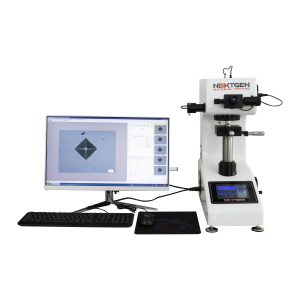 Vickers and Knoop Hardness TestersMacro Vickers Hardness TesterNG-5000 Series Macro Vickers Hardness Tester is built for accurate macrohardness measurement with standard digital, digital, and CCD optical-analysis...View product
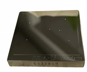 Vickers and Knoop Hardness TestersHardness Test Blocks, Indenters and AccessoriesHardness test blocks, indenters, and accessories support daily verification and reliable operation of metal hardness testing systems. The range includes certified...View product
 Vickers and Knoop Hardness TestersMetallography ConsumablesMetallography consumables cover the materials needed for sectioning, mounting, grinding, polishing, etching, and cleaning specimens before microscopic examination....View product