A tensile test pulls a specimen. A torsion test twists it, which is the loading a drive shaft, a helical spring, a fastener or a wire in a rope actually sees. Under one name, torsion testing of metals covers two different jobs. One is an elastic measurement: the shear modulus G of a bar or tube, from a few degrees of twist under ASTM E143. The other runs to destruction: wire twisted one way under ISO 7800 until it breaks, the result counted in whole turns.
Both run on a torsion testing machine with one grip that turns and one that holds, yet a setup that gives a good turn count can still give a poor modulus. This guide covers the mechanics, both standards, the fracture and the setup details that decide the number.
What a Torsion Test Measures
One end of a round specimen is held in a stationary grip while torque is applied to the other, and the basic output is a curve of torque against the angle of twist. The rest is geometry. Draw a straight line along the surface of a bar, twist one end through an angle φ, and the line tilts into a helix. The tilt is the shear strain at the surface, γ = r φ / L, where r is the radius, φ the angle in radians and L the length over which the twist is measured.
In the elastic range, shear stress rises linearly with radius, from zero on the axis to a maximum at the surface: τ = T r / J, where T is the torque and J the polar moment of inertia. For a solid bar J = π D⁴ / 32, so the surface stress is 16 T / (π D³). For a tube J = (π / 2)(ro⁴ – ri⁴), and thin-walled tubes are used where a nearly uniform stress is wanted, with τ = T / (2 π r² t) for mean radius r and wall thickness t.
Put together, the elastic twist is φ = T L / (J G). Torque against angle is a straight line of slope J G / L, and G comes from that slope as long as no part of the section has yielded. The surface yields first, and a seam, a lap or a scratch sits exactly where the stress is highest, which is why torsion results are so sensitive to surface condition.
Shear Modulus to ASTM E143
ASTM E143 is the test method for shear modulus at room temperature. The current edition, E143-20, is maintained by ASTM Committee E28 and uses SI units only. It covers the shear modulus of structural materials where creep is negligible compared with the strain that appears immediately on loading. Its scope also explains why the method exists: elastic properties such as shear modulus, Young’s modulus and Poisson’s ratio are not determined routinely and are generally left out of materials specifications, so a designer who needs G for a shaft or a spring usually has to measure it.
Shear modulus is useful for calculating compliance in torsion where the material follows Hooke’s law, the angle of twist proportional to the applied torque, and E143 names rotating shafts and helical compression springs as examples. It also lists what moves the result. On the specimen: residual stress, concentricity, wall thickness in tubes, deviation from nominal dimensions, previous strain history and size. In the test: axial position of the specimen, temperature and its variation, and maintenance of the apparatus. Interpretation of the data is a variable in its own right.
E143 refers to ASTM E6, E8/E8M, E111, E1012 and E2624, the practice for torque calibration. In published university procedures, one laboratory records torque every 2 degrees up to 30 degrees and fits a line by regression; another runs at about 5 degrees per minute and takes G from the slope of shear stress against shear strain. Either way, the angle goes into the formula in radians.
Measuring Twist on the Specimen, Not at the Grip
The angles are small. By our own arithmetic, a 10 mm steel bar with a 100 mm gauge length and a shear modulus of 80 GPa, loaded to a surface shear stress of 200 MPa, twists 0.05 rad, or 2.9 degrees, at a torque of about 39 N·m. A readout with 0.1 degree resolution gives about 29 steps across that whole linear range, and where the angle is measured matters as much as how finely.
Teaching procedures for E143-type tests read the twist over a gauge length on the specimen, with a troptometer, a mechanical twist gauge clamped to the bar at both ends of the gauge length, or with two clamp-on inclinometers whose readings are subtracted. An angle taken from the machine’s encoder also includes the wind-up of the shoulders, the grips and the drive train, and instrument makers’ application notes warn that this makes the modulus come out artificially low. Twist gauges have limits too: a troptometer is awkward to align and has to come off once the bar begins to deform plastically.
For an isotropic metal, G can be cross-checked with G = E / (2 (1 + ν)), where E is Young’s modulus and ν is Poisson’s ratio. In one published comparison, torsion on cold-rolled 1018 steel gave 11.74 and 12.37 Msi against 11.78 Msi, about 81 GPa, calculated from tensile data, and on 2024-T351 aluminium 3.96 and 4.15 Msi against 4.13 Msi, about 28.5 GPa, all within 5 %. Our guide to performing a tensile test on metals covers the tensile side of that check.
Because J grows with the fourth power of the diameter, a 1 % error in diameter becomes roughly 4 % in G, so laboratory procedures measure the gauge-section diameter to 0.02 mm or average at least five caliper readings. On the torque side, ASTM E2624 accepts indicated torques within ±1 % of reading and expects the applied torque to be traceable to the SI, the same principle as force calibration in our article on calibrating a UTM to ASTM E4.
Beyond Yield: What Torsion Shows That Tension Does Not
Once the surface yields, τ = T r / J no longer holds. In a solid bar yield begins at a torque of ½ π R³ τY, where τY is the shear yield stress, and beyond it the bar carries torque as an elastic core inside a plastic annulus whose stress no longer rises with radius. On the von Mises criterion the shear yield stress is about 0.577 of the tensile yield stress, a useful check. A true shear stress-strain curve past yield needs a correction from the slope of the torque-twist curve, usually the one associated with Nadai.
No neck forms in torsion, so the bar reaches much larger homogeneous deformation than in tension. That is why hot torsion is used to judge forgeability: the more twists before failure, the better the metal forges. At large angles an axial stress develops, and with both ends fixed a compressive axial load builds up as the twist grows, the Swift effect, so a grip free to move along the axis matters in large-strain work.
Torsion also loads the surface hardest, which makes it a natural check on surface quality. ISO 9649 states that its reverse torsion test is used to detect surface defects as well as to assess ductility, and ASTM A938 notes that the stress and strain conditions in torsion are sensitive to minor variations in materials.
Small Bolts That Cannot Be Pulled
Fasteners give torsion a third job. ISO 898-7 covers bolts and screws of property classes 8.8 to 12.9 with threads below M3, which have no breaking or proof loads in ISO 898-1, and short bolts and screws of 3 mm to 10 mm that cannot be tensile tested. The screw is clamped over at least two full threads, with at least one diameter of free thread below the head, and loaded in pure torsion with continuously increasing torque, free of head and thread friction. It passes if it holds to the minimum breaking torque, from 1.5 N·m for M3 in class 8.8 to 90 N·m for M10 in class 12.9.
The torquemeter scale may not exceed five times that minimum, and its maximum inaccuracy is ±7 % of it. By our arithmetic, a 200 N·m scale therefore suits only minimum torques of 40 N·m and up, which means M10 in all four classes and M8 from class 10.9, while an M6, at 13 to 17 N·m, needs a scale no higher than 65 to 85 N·m depending on the class.
Wire Torsion to ISO 7800
ISO 7800 is the simple torsion test for metallic wire: the wire is twisted about its own axis in one direction until it breaks or reaches a specified number of turns, and complete turns are counted. The current edition, ISO 7800:2012, confirmed in 2022, widened the 2003 scope of 0.1 mm to 10 mm to 0.1 mm to 14 mm. The number of turns required, Nt, comes from the product standard, not from ISO 7800.
The grips stay coaxial and apply no bending. One rotates, and the other may deflect angularly only as far as is needed to measure torque. Contraction of the wire must not be prevented, and the machine must be able to apply a tensile stress. Grip distance is adjustable and measurable, speed is held within 10 % of nominal, jaws are at least 55 HRC with parallel faces, and a protective shield is required, because wire can break into several pieces.
The free length scales with diameter: 200 d from 0.1 mm up to 1 mm, 100 d from 1 mm up to 5 mm, 50 d from 5 mm to 10 mm, and 25 d above 10 mm, for steel wire only, with 500 mm as the maximum, so a 3 mm wire is tested over 300 mm. Wire is straightened without damaging or twisting its surface, and wire with a sharp kink is not tested. Unless otherwise specified, a constant tensile stress of no more than 2 % of the nominal tensile strength keeps it on the axis; steel wire over 10 mm needs none. The annex recommends smooth jaws below 0.3 mm, lightly serrated up to 3 mm, and V-grooved up to 10 mm.
Speed Is Set in Turns per Second
ISO 7800 gives its nominal speeds in turns per second, by material and size. For steel wire they run from 1 turn per second below 1 mm, through 0.5 up to 5 mm and 0.25 up to 10 mm, to 0.1 above 10 mm, with higher values allowed for steel that is not sensitive to strain rate. Copper alloys run up to 5 turns per second for the finest wire, and aluminium alloys at 1. The test is meant to be isothermal, and for rate-sensitive wire the standard gives 60 °C as an example limit on the temperature. Ambient is 10 °C to 35 °C, or 23 ± 5 °C for controlled tests. When torsion testing machines are compared for wire, speed in turns per second at your wire sizes is the first figure to check.
Counting Turns and Judging Validity
A coloured line drawn along the wire winds into a helix, one pitch per turn, so the count can be checked afterwards. If the count meets the product standard, the wire passes wherever it broke. If it falls short and the break is within 2 d of a grip, the test is invalid and is repeated. Wire often breaks into several pieces from springback after the first fracture, which is usually smooth and perpendicular to the wire axis, and only that first fracture is evaluated. The report gives the material and heat number, size, preparation, free length, speed, tensile stress and number of turns.
Two related methods often sit beside it. ISO 9649:2023, reverse torsion for wire from 0.3 mm to 10 mm, twists a set number of turns one way and then the other, at no more than 1 turn per second, or 0.5 from 5 mm, then examines the wire by eye for surface defects and cracks. ASTM A938, current as A938-18(2024), covers wire torsion in US customary units and controls straightening, test length, alignment and straightening tension, speed and turn counting, with acceptance limits from the product specification.
Reading a Torsion Fracture
The fracture surface shows which stress won. A ductile metal in torsion breaks on a plane perpendicular to the axis of twist, the plane of maximum shear stress, and the break looks flat and square across the bar. A brittle material such as grey cast iron, chalk or concrete breaks along a helix at 45 degrees to the axis, the plane of maximum tensile stress.
For wire, the informative annex of the 2003 edition of ISO 7800 sorts fractures into three types. Type 1 is a normal fracture without cracks: 1a smooth and perpendicular to the axis, 1b brittle on a 45 degree plane. Type 2 has local cracks attributed to material defects. Type 3 has spiral cracks along most of the length, which appear after only 3 to 5 turns and are easiest to see then.
The 2012 edition keeps a fracture annex, now Annex B, and notes that for small diameters some classes, such as 2b and 3b, cannot be told apart. Fracture evaluation is optional in ISO 7800, so a class goes into a report where the product standard or customer asks for it, with the edition named.
Setting Up a Torsion Test
Most of the errors that spoil a torsion result are fixed in place before the first degree of twist. Gripping matters as much as it does in tension, and our guide to grips and fixtures covers wire grips and slip at the clamp from the tensile side.
On range, each GenTor capacity is specified from 20 % of its full range, so a 6,000 N·m frame is the wrong choice for a 30 N·m fastener. Choose the capacity from the highest torque the test must reach, then check the lowest reading against the bottom of the range. Closed-loop control by angle or torque, with a timed hold, gives the same test next week as this week, as our article on testing machine software explains for universal machines.
Torsion Testing on the NextGen GenTor
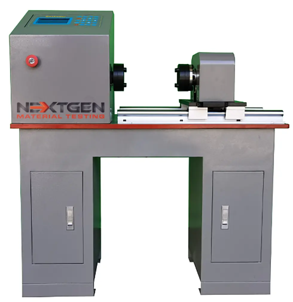
The GenTor horizontal torsion tester is our torsion testing machine for metals. It is computer controlled and built on a horizontal load frame: one grip turns, the other stays fixed and carries the torque sensor, and the frame takes the reaction. Long specimens sit unsupported between the grips, and the stiff frame keeps its own wind-up out of the reading. Five capacities, from 200 N·m to 6,000 N·m, share one platform. Torque comes from the sensor at the fixed grip and angle from an optical encoder at the moving grip end, with torque accuracy within ±1 % from 20 % of each range and an angle resolution of 0.1 degree.
The software runs in closed loop by constant rotation angle or constant torque, holds a target for a set time, and reports torque, yield torque, maximum torque, torque strength and angle as it draws the curve. The GenTor takes bar, wire and shaft stock, finished parts, and non-metallic and composite specimens. Our overview of the GenTor covers the machine in more detail.
Configuration depends on which torsion job you run, and we settle it before quoting. For shear modulus to ASTM E143, the machine reads the rotation of the moving grip, so the questions are how twist over the gauge length will be measured and how the ends are held without bending. For wire to ISO 7800 or ASTM A938, they are the speed in turns per second your sizes need, how the wire is kept straight under tension while free to shorten, the turn count and the jaw type. Tell us those, and we will say plainly what fits and where your method needs more than the standard configuration.
 Flexural (Bend) Testing Explained: 3-Point vs 4-Point, Standards, and SetupFlexural (bend) testing explained: what it measures, three-point vs four-point setups, the standards for plastics, metals, composites and concrete, and how to choose the right fixtures and...Read the articleGenTest Software Setup Guide for NextGen NG-EML Universal Testing MachinesGenTest setup affects the full UTM testing workflow: method storage, PC-to-controller communication, user permissions, simulation files, live data acquisition, and report output. This guide follows the GenTest setup video step by step for NextGen NG-EML electromechanical universal testing machines. It covers installation, license activation, workspace configuration, UTM controller connection, safety and peripheral setup, user management, DEMO Mode, simulation files, Control Panel setup, Quick Test, and test method creation. GenTest is the software layer where the test method, machine connection, operator input, live data, calculated results, and report output come together. For operators, service teams, QA/QC labs, and R&D users, the goal is to...Read the articleBrinell, Rockwell, Vickers, or Microhardness: Which Test Makes Sense for Your Application?Choosing a hardness test starts with the part itself. Material type, section thickness, geometry, surface condition, inspection purpose, and required testing speed all affect which method will produce a reliable result. Brinell, Rockwell, Vickers, and microhardness methods work differently, so they are not equally suitable for the same component or the same quality task. Brinell, Vickers, and Knoop are based on the size of an indentation, while Rockwell is based on indentation depth. That difference directly affects how the result is obtained and where the method fits best. In production and lab work, problems usually appear when the test method does not fit the application. A part may be too thin for the selected load, the surface may be too rough...Read the article
Machines Behind This Article
 Torsion Testing MachinesGenTor – Horizontal Torsion TesterNextGen GenTor is a horizontal torsion tester for measuring torque, torsion angle, deformation, and torsional strength in metals and components. With capacity...View product
 Electromechanical Universal Testing Machines for Rubber TestingNG-EML Series C – Dual-Column Universal Testing Machine (5–50 kN)NG-EML Series C is a dual-column electromechanical universal testing machine available in bench-top and floor-standing formats from 5 kN to 50 kN. Built for...View product