A Rockwell hardness number tells you very little until you know the letters that come with it. A reading of 60 on one scale and a reading of 60 on another describe different materials, tested with a different indenter under a different force, and neither can be compared with the other until someone knows which scale produced it. A drawing that asks for 60 HRC is specifying a whole test: a diamond indenter, a total force of 150 kgf and a depth measurement made in a defined way.
ASTM defines thirty Rockwell scales. Picking the right one is a decision that can go wrong without any warning, because the wrong scale does not produce an error message. It produces a number, and that number looks just as plausible as a valid one.
This article explains what the scale letters mean, how the regular and superficial scales differ, and how to match a scale to the material, the thickness and the shape of the part. The test cycle itself is covered step by step in our article on the Rockwell hardness test, and if you are still weighing Rockwell against Brinell and Vickers, our guide to choosing a hardness testing method for reliable QC is the better place to start.
What a Rockwell Number Actually Measures
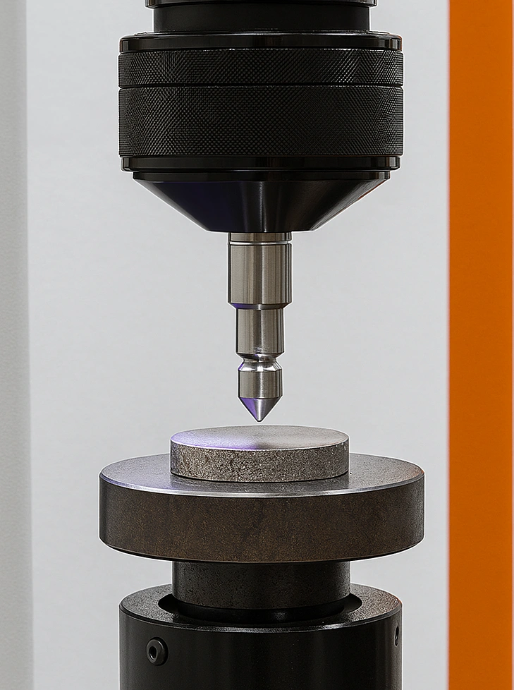
Rockwell is a depth test. The indenter is first brought into contact under a small preliminary force, which seats it and sets the zero point for the measurement. The force is then raised to the total force, held briefly and brought back down to the preliminary force. The hardness value comes from one quantity: how much deeper the indenter sits at the end of the cycle than it did at the zero point. That permanent increase in depth is written as h.
The machine turns h into a number on a scale that runs the opposite way to depth. A harder material lets the indenter in less, so h is smaller and the Rockwell number is higher. On the diamond scales the number is 100 minus h divided by 0.002 mm. On the regular scales that use a ball the constant is 130 instead of 100, and on the superficial scales the divisor becomes 0.001 mm. One Rockwell point is therefore 0.002 mm of depth on a regular scale and 0.001 mm on a superficial one, which gives a sense of how small the distances are that a tester has to resolve.
Because the result is a depth difference, anything that changes depth without changing the material changes the number as well: a worn indenter, a part that moves on its support, or a hold time that differs from the one the standard sets. The NIST guide to Rockwell hardness measurement documents measurable shifts in HRC readings when the dwell at the preliminary or the total force is changed, which is why timing belongs to the procedure rather than to an operator’s habit.
Regular and Superficial Scales Work at Different Forces
The thirty scales fall into two families. The regular scales use a preliminary force of 10 kgf (98.07 N) and a total force of 60, 100 or 150 kgf (588.4, 980.7 or 1471 N). The superficial scales use a preliminary force of 3 kgf (29.42 N) and a total force of 15, 30 or 45 kgf (147.1, 294.2 or 441.3 N). A superficial scale is named by its total force and a letter for the indenter, so HR30N means a diamond at 30 kgf and HR15T a 1/16 inch ball at 15 kgf.
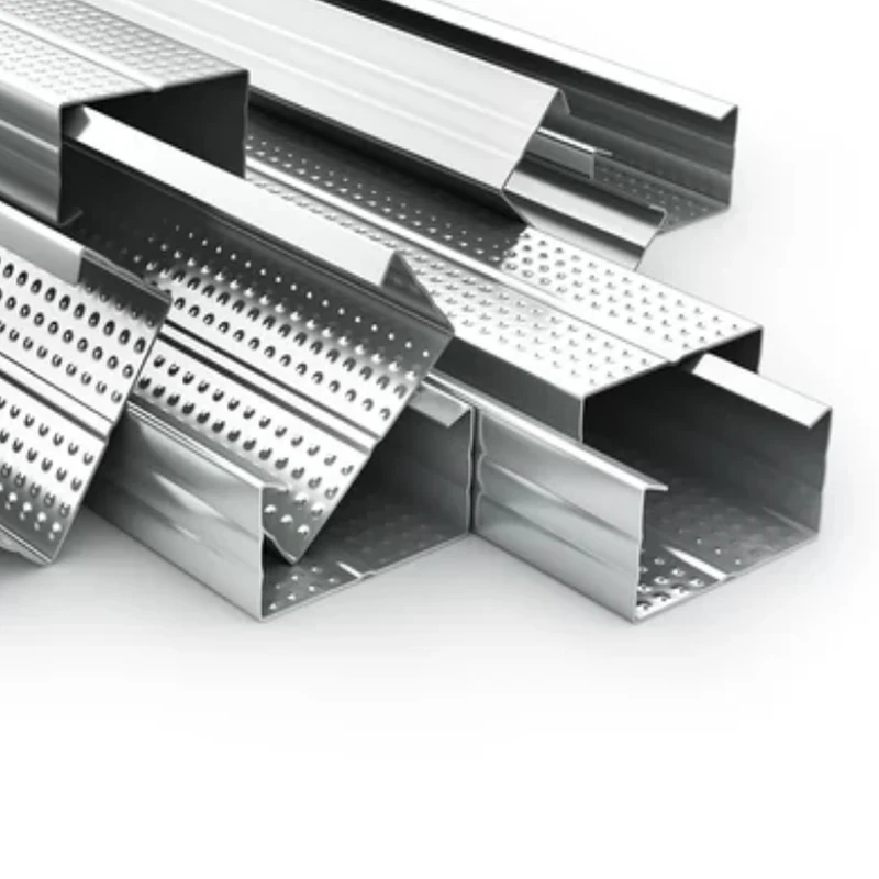
The lighter family exists for material that cannot carry a regular test: thin sheet, small parts and shallow hardened layers, where a heavier indentation would reach through the feature being measured. ASTM’s own list of applications describes the N scales as counterparts of the A, C and D scales for thinner material or case depth, and the T scales as counterparts of the B, F and G scales for thinner material.
Counterparts are not equivalents. A reading on a superficial scale and a reading on a regular scale are different measurements, and moving between them takes a conversion table such as those in ASTM E140. Conversions are empirical, and NIST’s advice on them is direct: where earlier data exist, test on the scale that produced them as long as a valid test is possible there, because a converted value is less accurate than the original measurement. Our ASTM E18 page covers the method that both families are tested under.
Thirty Scales Built From Five Indenters and Six Forces
Each Rockwell scale pairs one indenter with one total force. Five indenters are in use, a spheroconical diamond and balls of 1/16, 1/8, 1/4 and 1/2 inch diameter, and there are six total forces, three regular and three superficial. The map below lays out all thirty combinations and marks the ones the international standard recognizes.
ISO 6508-1:2023 covers fifteen of these scales, the nine regular scales from A to K plus the 15N, 30N, 45N, 15T, 30T and 45T superficial scales, and it uses the two smaller balls. ASTM E18 adds the scales built on the 1/4 and 1/2 inch balls and the superficial W scales. A laboratory that works to both standards, or ships to customers who cite either, should confirm that the scale on the drawing exists in the standard named on the purchase order before the first part is tested.
Ball size follows the material. As NIST summarizes it, the ball gets larger as the material gets softer and thinner, and for the scales aimed at very soft or thin materials ASTM’s guidance is to use the smallest ball and the heaviest force that do not produce an anvil effect. The ball material matters too. Steel balls tend to flatten over time at the point of contact, particularly on harder materials, and a flattened ball does not penetrate as deeply, so it reads the material harder than it is. That is the reason practice has moved toward tungsten carbide balls.
Matching the Scale to the Material in Front of You
For metals, ASTM’s table of typical applications is the usual starting point. HRC, the diamond at 150 kgf, is listed for steel, hard cast irons, pearlitic malleable iron, titanium, deep case hardened steel and other materials harder than HRB 100. HRB, the 1/16 inch ball at 100 kgf, covers copper alloys, soft steels, aluminum alloys and malleable iron. HRA uses the diamond at 60 kgf for cemented carbides, thin steel and shallow case hardened steel, and HRD sits between the two for thin steel, medium case hardened steel and pearlitic malleable iron.
The remaining regular ball scales stretch the range further. HRE, a 1/8 inch ball at 100 kgf, is listed for cast iron, aluminum and magnesium alloys and bearing metals; HRF, a 1/16 inch ball at 60 kgf, for annealed copper alloys and thin soft sheet; HRG, the same ball at 150 kgf, for malleable irons and copper-nickel-zinc and cupronickel alloys; and HRH, a 1/8 inch ball at 60 kgf, for aluminum, zinc and lead. A few habits from NIST’s guidance settle many of the choices that remain.
Plastics fall outside ASTM E18 altogether. ASTM D785 applies the Rockwell principle to plastics and electrical insulating materials with specified ball indenters and corresponds to ISO 2039-2, and because some plastics keep deforming under load, the procedure chosen and its timing can move the reading considerably. The standard also cautions against treating the result as a direct measure of wear or abrasion resistance.
Thickness, Curvature and Spacing Can Void a Good Reading
A scale can suit the material and still be wrong for the part. As the indenter goes in, the metal around it deforms plastically to a depth well below the indentation itself. If that zone reaches through a thin part to the anvil, the material flows at the interface and the test gives an erroneous result, and nothing on the display says so.
Thin Sheet and Hardened Cases
For sheet and strip, the remedy is a lighter force or a superficial scale, chosen so the deformed zone stays inside the material. For case hardened parts the same logic applies to the layer rather than the part: when the case is what is being measured, the scale is chosen by the thickness of the case. Small features such as the heat affected zone of a weld call for a force and indenter that leave an indentation small enough not to be influenced by the zones next to it. Where even the lightest superficial test is too large for a layer, the measurement moves to microindentation, which our article on measuring case depth covers in detail.
Round Bars, Edges and Neighboring Indentations

Width limits a test the way thickness does, because the deformation spreads sideways as well as down. An indentation placed too close to an edge, or to an earlier indentation, lands in material that has already been deformed and work hardened, and the reading shifts, which is why the standards set minimum distances for both.
Curved parts need the right support. Flat material goes on a flat anvil, the convex side of curved material rests in a V-shaped or double-roller anvil, and small or thin samples and parts without a flat underside go on a spot anvil. On a round part the indentation belongs at the apex of the convex surface, and readings taken on convex cylindrical surfaces are subject to the curvature corrections given in the standard.
Daily Checks on a Block of the Same Scale
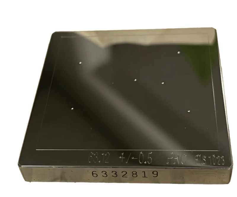
A Rockwell tester can drift with nothing looking wrong, and the daily check is how a laboratory finds out. NIST’s guidance is to run it at least once on each day of testing, after the indenter and the anvil have been seated, using reference test blocks, ideally of the scale and hardness level the day’s parts will be tested at. Where the anvil the parts need cannot hold a block, a V-anvil for round work being the usual example, the laboratory keeps parts of known hardness that can be tested on that anvil instead.
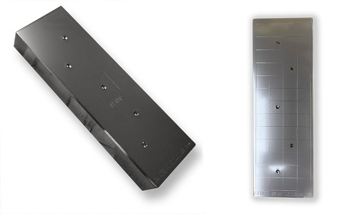
The blocks sit in a traceable chain. ISO 6508-2 covers the verification of testing machines and indenters, and ISO 6508-3 the calibration of the reference blocks used for indirect and daily verification. On the block itself, indentations should be spread at random across the surface rather than packed in from one side, so that the check compares the tester with the block’s certified average and not with one corner of it. Our range of certified hardness test blocks and indenters covers the Rockwell scales along with Brinell, Vickers and Knoop.
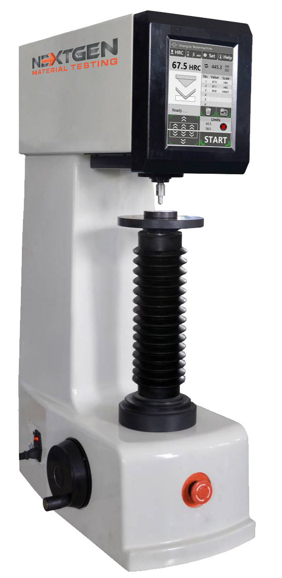
Choosing the tester comes down to the scales the work needs. A laboratory that tests hardened steel and soft alloys on the regular scales has different needs from one that also tests sheet, strip and case hardened parts on the superficial scales, and a production line that checks many parts a day has different needs again. Our Rockwell hardness testers cover all three, and where the same laboratory also runs Brinell and Vickers, a universal hardness tester carries the three methods on one frame.

 Flexural (Bend) Testing Explained: 3-Point vs 4-Point, Standards, and SetupFlexural (bend) testing explained: what it measures, three-point vs four-point setups, the standards for plastics, metals, composites and concrete, and how to choose the right fixtures and...Read the articleGenTest Software Setup Guide for NextGen NG-EML Universal Testing MachinesGenTest setup affects the full UTM testing workflow: method storage, PC-to-controller communication, user permissions, simulation files, live data acquisition, and report output. This guide follows the GenTest setup video step by step for NextGen NG-EML electromechanical universal testing machines. It covers installation, license activation, workspace configuration, UTM controller connection, safety and peripheral setup, user management, DEMO Mode, simulation files, Control Panel setup, Quick Test, and test method creation. GenTest is the software layer where the test method, machine connection, operator input, live data, calculated results, and report output come together. For operators, service teams, QA/QC labs, and R&D users, the goal is to...Read the article
Machines Behind This Article
 Rockwell Hardness TestersGenRock NG-150 Series – Rockwell Hardness TesterGenRock NG-150 Series is an advanced Rockwell hardness tester for regular and superficial hardness testing of metals and alloys. Available in manual and automatic...View product
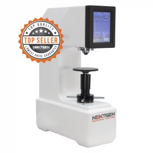 Rockwell Hardness TestersNG-RockGen DGEN Series – Digital Rockwell Hardness TesterNG-RockGen DGEN Series is a digital Rockwell hardness tester for measuring metal hardness by indentation depth under standard Rockwell loading. Available in...View product
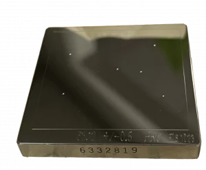 Rockwell Hardness TestersHardness Test Blocks, Indenters and AccessoriesHardness test blocks, indenters, and accessories support daily verification and reliable operation of metal hardness testing systems. The range includes certified...View product
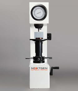 Rockwell Hardness TestersNG-RockGen Analogue Series – Rockwell Hardness TesterNG-RockGen Analogue Series is a Rockwell hardness tester for routine hardness measurement of metals, available in manual and electronic models. It supports HRA,...View product
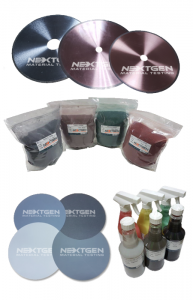 Rockwell Hardness TestersMetallography ConsumablesMetallography consumables cover the materials needed for sectioning, mounting, grinding, polishing, etching, and cleaning specimens before microscopic examination....View product
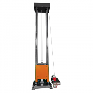 Metal TestingDWT-1800 – Computer-Controlled Drop Weight Impact TesterDWT-1800 is a computer-controlled drop weight impact testing machine for evaluating impact resistance in metal and non-metal materials. Capable of high-energy tests...View product
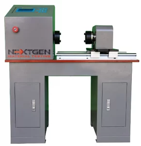 Metal TestingGenTor – Horizontal Torsion TesterNextGen GenTor is a horizontal torsion tester for measuring torque, torsion angle, deformation, and torsional strength in metals and components. With capacity...View product
 Metal TestingHeavy-Duty Bending Fixtures for Hydraulic Flexural TestingHeavy-duty bending fixtures support high-force flexural testing of metals, composites, ceramics, reinforcing bars, and structural materials on hydraulic universal...View product
 Metal TestingNG-AutoPol – Automatic Longitudinal Polisher for Tensile SpecimensNG-AutoPol is an automatic longitudinal polishing system for metallic tensile and fatigue specimens. It removes machining marks, grinding stress, and residual...View product
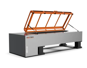 Metal TestingNG-EML Series H – Horizontal Universal Testing MachineNG-EML Series H is a horizontal universal testing machine line for tensile, proof load, elongation, and breaking force testing of long or difficult-to-handle...View product
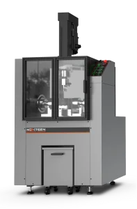 Metal TestingNG-FLX Series A – Flexural and Bend Testing SystemNG-FLX Series A is an electromechanical flexural and bend testing system for controlled sheet metal bending, three-point bend testing, flattening tests, ductility...View product
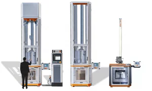 Metal TestingNG-FWT1 and NG-FWT2 – Drop Weight Impact Testers (up to 2000 J)NG-FWT1 and NG-FWT2 are low-capacity vertical drop weight impact testers for controlled falling-weight tests up to 2000 J. They help evaluate impact resistance,...View product