A concrete cylinder is cast to measure one number, and most of the work that decides whether that number is right happens at its two ends. The compression machine loads the specimen through its end faces. If those faces are not flat, or not square to the axis, the platens touch a high spot or an edge first, the load runs through part of the section instead of all of it, and the cylinder breaks early. The report then shows a low strength for a concrete that was never weak.
There are three accepted ways to give a cylinder or a core usable ends: grind them flat, cap them with a bonded material such as sulfur mortar, or seat them in unbonded elastomer pads held in steel retainers. ASTM C39 lists all three as routes to a specimen it will accept. They are not interchangeable, though, and the differences grow with the strength of the concrete. This guide sets out what each method requires, where each one runs out, and how cores add their own complications.
What the Ends Have to Achieve
The requirement behind every method is the same: two load-bearing faces that are plane and perpendicular to the specimen’s axis. Free summaries of C39 from FHWA and NRMCA give the figures most laboratories work to: ends plane within 0.050 mm (0.002 in), and no departure from perpendicularity of more than 0.5 degree, which is about 1 mm across a 100 mm diameter. A specimen whose ends miss those limits is sawed or ground until it meets them, or capped under ASTM C617 or, where permitted, ASTM C1231.
Half a degree sounds generous until it is drawn. On a 150 mm cylinder it is a wedge of about 1.3 mm from one side of the face to the other, more than twenty times the planeness limit. A platen meeting that face touches one edge first and has to crush it before the rest of the section carries load. The European standard expresses the same idea in proportion to size: EN 12390-1 sets the flatness of a load-bearing surface at 0.0006 times the diameter, about 0.09 mm on a 150 mm cylinder.
How much a flaw costs depends on the strength of the concrete, and the effect has been known for a century. In the tests reviewed by NIST, an end convexity or concavity of 0.08 mm made no difference on concretes of 15 to 24 MPa, but deviations of 0.25 mm or more reduced strength significantly, and the loss grew as the concrete got stronger. The stronger and stiffer the concrete, the less a small error in the end is forgiven.
Laboratories catch most bad ends before the specimen reaches the machine. The Washington State DOT checklist for cylinder compression testing under AASHTO T 22 has the technician check the ends of each specimen for plane and for perpendicularity, and send any that fail to the saw, the grinder or the capping station. State technician training adds a quicker screen: a carpenter’s square laid across the end, and if the highest and lowest points differ by more than about 3 mm (1/8 in), the cylinder is cut or ground before any cap goes on. The diameter is measured twice at mid-height as well, and a specimen whose two readings differ by more than 2 percent is not tested.
Three Ways to Make the Ends Right
Each method solves the same geometric problem in a different way. Grinding removes material until the face is flat and square. A bonded cap adds a thin layer of stiff material that fills the irregularities and presents a new flat face. An unbonded pad adds a soft layer that flows into the irregularities under the first load, held in a steel ring so it cannot spread sideways.
Grinding

Grinding produces an end that is concrete all the way to the platen, with nothing between them to deform, set, age or be qualified. That is its main advantage and the reason the European core standard, EN 12504-1, notes that end preparation by grinding is recommended as the most precise method. AASHTO went a step further in 2024 with R 119M/R 119, a standard practice devoted to grinding the ends of cylindrical concrete specimens, written with ultra-high-performance concrete in mind, and the 2026 edition of C39 now lists it among the practices that prepare specimens for testing. A ground cylinder is ready to test as soon as it is ground, and the result does not depend on the age or strength of a capping compound.
Grinding is wet work. A diamond wheel cuts the face under a water spray, which also keeps the dust down, and the machine has to hold the specimen square while the wheel passes across it. That is what separates a grinder built for this job from a general surface grinder: the fixture decides the perpendicularity, and the wheel decides the flatness.
Bonded Caps: Sulfur Mortar, Gypsum and Cement Paste
ASTM C617 covers bonded caps of neat cement paste on freshly molded cylinders and of high-strength gypsum paste or sulfur mortar on hardened cylinders and drilled cores. Bonded caps remain common: the FHWA laboratory manual estimates that about a quarter of US laboratories use them as their primary end treatment. They work well when they are thin, strong and bonded across the whole face. Free state DOT training material on C617 describes the limits: for cylinders from 500 to 7000 psi, a cap no thicker than 8 mm anywhere and 6 mm on average, made of material with a strength of at least 5000 psi or the cylinder’s strength, whichever is greater; above 7000 psi, no thicker than 5 mm and 3 mm on average, and at least as strong as the concrete or qualified against ground or paste-capped companions.
Sulfur caps also need time. The same training material calls for at least 2 hours of hardening before testing below 5000 psi and 16 hours at 5000 psi and above unless qualification shows less. Pure sulfur is a poor capping material on its own: the NIST review records a compressive strength of about 16 MPa and a stiffness around a tenth of concrete’s, which is why capping compounds carry sand or fly ash. And sulfur capping carries a hazard grinding does not. The melting pot must sit under a hood or next to an exhaust fan, because sulfur mortar contaminated with oil or other organic material can produce hydrogen sulfide, which is lethal in high concentrations and cannot be trusted to give itself away by smell.
Most cap problems are found by routine checks rather than by a low result. The FHWA manual names the usual errors: voids where moisture under the cap turned to vapor, and misuse of the alignment device, which loads the specimen off-center. Against them, the training material sets clear controls: the alignment device holds the cap within 0.5 degree of perpendicular and no more than 1.6 mm (1/16 in) off-center, and at least three capped specimens per run, at its start, middle and end, are checked with a straightedge and feeler gauge across three diameters. The capping material is tested on 50 mm (2 in) cubes for each new lot and at least every three months, sulfur mortar is reused no more than five times and not at all for concrete above 5000 psi, and above 7000 psi a material weaker than the concrete is qualified on 30 cylinders: 15 capped with it and 15 ground or capped with neat cement paste, with the first set averaging at least 98 percent of the second.
Unbonded Caps: Neoprene Pads in Steel Retainers
ASTM C1231 allows unbonded caps on molded cylinders and on drilled cores in place of C617 caps. An elastomer pad, typically about 13 mm thick, sits in a steel retainer whose inside diameter is slightly larger than the specimen. On the first loading the pad deforms to follow the end, and the retainer stops it spreading. There is nothing to melt, mix or wait for, which is why pads are popular in high-volume laboratories.
Their range is fixed by the standard. Unbonded caps are not used for acceptance testing of concrete below 10 MPa or above 80 MPa. Within that range, neoprene pads of a stated hardness can be reused a set number of times without qualification up to a strength limit, and above it, qualification is required. The DOT training material gives the usual table: 50 durometer pads for 1500 to 6000 psi, 60 for 2500 to 7000 psi, 70 for 4000 to 7000 psi, all without qualification and up to 100 uses, and 70 durometer pads from 7000 to 12,000 psi only with qualification and up to 50 uses. ASTM also warns that specimens tested with unbonded caps rupture more violently than comparable specimens with bonded caps, so containment around the platens matters more.
Pads cope with rougher ends than bonded caps do. NRMCA’s guidance puts the limit for bonded caps at surface defects under about 3 mm and for unbonded systems at about 5 mm, and anything worse is sawed or ground before the pad goes on.
Pads trade the capping station for bookkeeping. The pad is 13 mm (1/2 in) thick within 1.6 mm, its retainer has an inside diameter of 102 to 107 percent of the cylinder’s, and a pad outside those limits or past its reuse count is replaced. Laboratories keep a record of the date each pad went into service, its durometer and its number of uses. Qualification pairs cylinders at both the highest and the lowest strengths expected, ten pairs at each level, one of each pair with pads and the other ground or capped, and the pad average must reach at least 98 percent of its companions. The specimen’s alignment is checked after load is applied but before 10 percent of the expected maximum, since FHWA notes that with unbonded caps a corner fracture can occur before the cylinder reaches its ultimate capacity.
When the Method Changes the Number
The clearest data on grinding against capping comes from a NIST study sponsored by FHWA, which tested 100 by 200 mm and 150 by 300 mm cylinders at nominal strengths of 45 and 90 MPa, with ends either capped with sulfur mortar or ground. On average the ground cylinders were 2.1 percent stronger. At 45 MPa the end preparation made no difference. At 90 MPa grinding gave up to 6 percent higher strength in some combinations, with caps under 4 mm thick, and the authors expected larger differences with thicker caps. Their recommendation for concrete above 50 MPa was a performance requirement that a capping method should not average lower than grinding.
Another study at 50, 75 and 120 MPa found that sulfur caps applied 2 hours before the test read 2 to 7 percent below ground ends, while caps applied 7 days before matched them, except for thick caps on the 120 MPa concrete. The mechanism is the one the older literature describes: a cap that is softer than the concrete squeezes outward under load, adds lateral tension at the end of the specimen and lowers the reading. A thin, stiff, fully hardened cap behaves almost like concrete. A thick or young one does not.
Read together, the standards and these studies give a practical picture. For ordinary strengths, all three methods are recognized and, done correctly, agree closely. As strength rises, the window narrows: caps have to be thinner, stronger, older and qualified, pads need qualification and lose reuses, and above 80 MPa pads are excluded altogether. Grinding is the one method that does not get harder as the concrete gets stronger, which is why it is the reference method in the studies above and the method AASHTO standardized for ultra-high-performance concrete.
Grinding has a limit of its own, and the early UHPC work shows where it lies. In FHWA’s 2006 study of ultra-high-performance concrete, 76 by 152 mm cylinders expected to exceed 83 MPa were ground, while weaker mixes were sulfur-capped, because at those lower strengths the wheel tended to pull fibers out and leave an uneven end. Planeness was checked on a flat steel plate with a dial gauge reading to 0.025 mm, and ends that failed were reground.
Cores Are a Different Specimen
Drilled cores bring every end problem of a molded cylinder plus several of their own. ASTM C42 covers obtaining, preparing and testing them, and its significance section is candid about how many things move the result: the position of the core in the element, the direction it was drilled, the moisture in it at the time of test, and the ratio of its length to its diameter. A core generally tests lower than a properly molded and cured cylinder of the same concrete at the same age, with no single relationship between the two.
Moisture is the reason cores are handled in a fixed sequence. ASTM notes there is no conditioning procedure that reproduces the moisture state of the concrete in the structure; the procedures exist to make results reproducible between laboratories. As the free DOT summaries of the AASHTO practice describe it, the core is wiped and sealed in a plastic bag soon after drilling, trimmed and ground while any water from those steps can still dissipate, and kept sealed for at least five days before testing. Wet grinding after the sealed period would put water back into the ends, so the order matters.
Length matters as much as the ends. A core is normally trimmed to a length of about twice its diameter, and the C39 correction factors apply when the ratio falls to 1.75 or below: 0.98 at 1.75, 0.96 at 1.50, 0.93 at 1.25 and 0.87 at 1.00. Under the FHWA description of C42, a core for strength testing is at least 94 mm in diameter, and if it is capped, the length is measured again with the caps on. EN 12504-1 prefers a length-to-diameter ratio of 2.0 to compare with cylinders or 1.0 to compare with cubes, and it rules out sulfur or calcium aluminate cement caps when the expected strength is above 50 MPa for a 2:1 core or 60 MPa for a 1:1 core. For strong concrete in Europe, the core ends are ground.
A worked example shows how much can ride on these details. Suppose three cores 94 mm in diameter can only be trimmed to 141 mm, an L/D of 1.50, and they break at 31.0, 32.5 and 29.6 MPa. Each reading is multiplied by 0.96, giving 29.76, 31.20 and 28.42 MPa, an average of 29.79 MPa. A note in C42 cites the ACI 318 criterion: concrete represented by cores is considered structurally adequate if the average of three cores is at least 85 percent of the specified strength and no single core is below 75 percent. For a specified 35 MPa, those limits are 29.75 and 26.25 MPa, so these cores pass by 0.04 MPa. Had the weakest core lost 3 percent to a poorly prepared end, the average would have dropped to 29.51 MPa and the verdict would have reversed. The factors have limits too: a 2016 Auburn University report for the Alabama DOT notes that they are valid for concrete of about 14 to 41 MPa (2000 to 6000 psi), with no guidance from there to 10,000 psi.
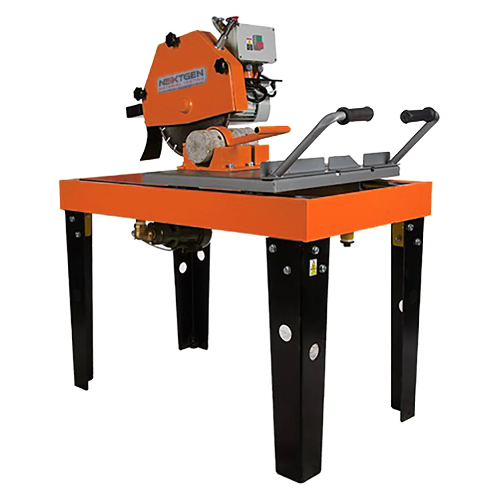
Cutting the core to length is the first precision step, not a rough one. A saw cut that leaves the end well off square means more grinding afterward and a shorter specimen. Our article on the core cutter and saw for rock, concrete and masonry covers that step, and for rock cores, where the tolerances are much tighter than for concrete, our guide on rock core preparation and end grinding goes through the rock standard in detail.
Choosing an End Preparation for Your Laboratory
The choice usually comes down to four questions. What strengths do you test, and do any exceed 50 MPa? Do you test cores as well as molded cylinders? How many specimens a day go through the compression machine? And who in the laboratory handles molten sulfur today, under what ventilation?
A laboratory testing ordinary structural concrete in volume can run pads or caps well, provided the pads are tracked for reuse and the caps are checked for planeness and age. A laboratory that tests high-strength concrete, cores for structural assessment, or anything that may be disputed later gains the most from grinding: the method that does not narrow with strength, needs no qualification program for a capping material, takes no curing time, and removes the sulfur pot from the building. The cost is a machine and a few minutes per specimen, set against capping material, fume control, pad replacement and the risk of a low result that was really a bad end.
NextGen supplies the preparation side of that decision: grinders that bring both ends of cylinders, cores and cubes into tolerance, and saws that cut cores to length first. The rock mechanics testing equipment range shows the full preparation line, from cutting to grinding.
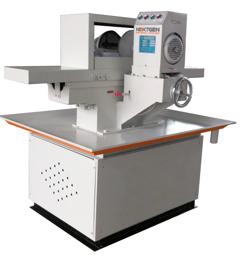
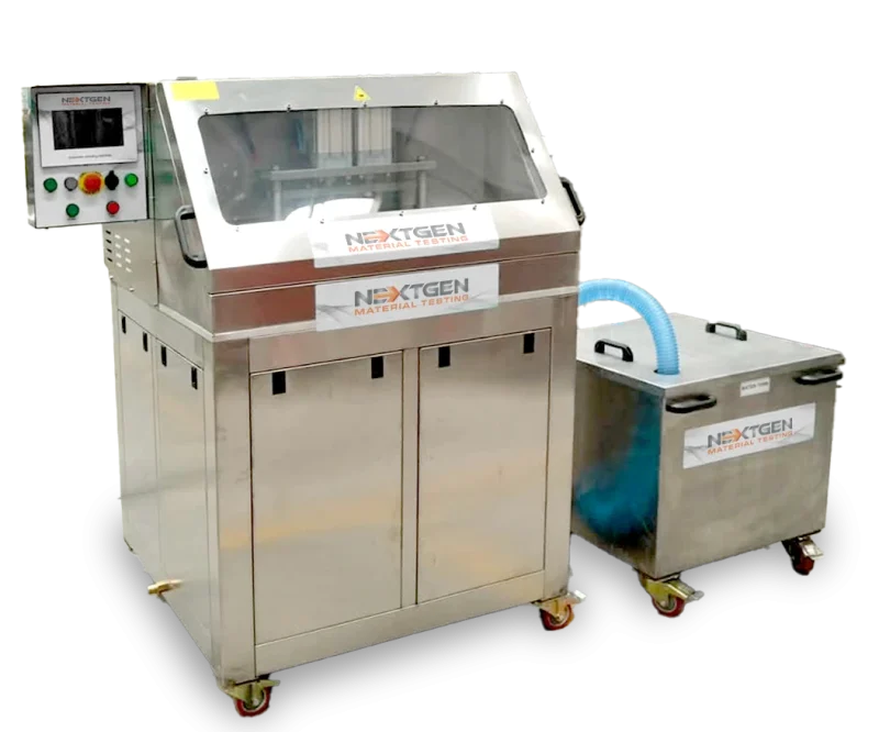
For a closer look at the semi-automatic machine, our NG-CoreGrind 1000 review goes through its adapters and setup.
Machines Behind This Article
 Rock Specimen PreparationNG-CoreGrind 2000 – Double-Faced Rock Core GrinderNG-CoreGrind 2000 is a double-faced rock core grinder for preparing flat, parallel specimen ends before rock mechanics and concrete testing. It is built to grind...View product
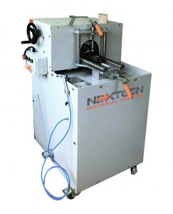 Rock Specimen PreparationNG-CoreGrind 1000 – Semi-Automatic Core Grinding MachineNG-CoreGrind 1000 is a semi-automatic core grinding machine for preparing rock and concrete specimens as an alternative to traditional rubber or sulfur capping....View product
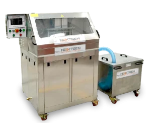 Rock Specimen PreparationCoreGrind 3000 – Automatic Core Grinding MachineCoreGrind 3000 is a fully automatic core grinding machine for preparing rock core specimens before geotechnical and rock mechanics testing. It uses a 7-inch...View product
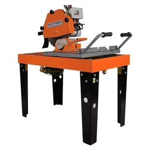 Rock Specimen PreparationRock Core Cutter and Masonry SawThe Rock Core Cutter and Masonry Saw is a universal cutting system for concrete, rock cores, and irregular rock samples. Available with 450 mm or 600 mm blade...View product
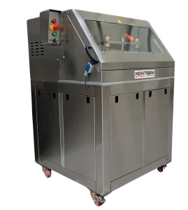 Rock Specimen PreparationCoreTrim 3000 – Core Cutting MachineCoreTrim 3000 is a fully automatic core cutting machine for preparing cylindrical rock specimens before laboratory testing. It cuts cores from 38 to 100 mm...View product
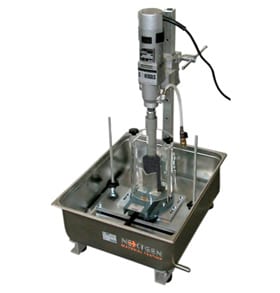 Rock Specimen PreparationLaboratory Coring Machine and BitsThe Laboratory Coring Machine and Bits system is designed for extracting clean cylindrical cores from rock, concrete, and similar hard materials. With an 1800 W...View product