A direct shear test looks like the simplest measurement in a geotechnical laboratory. A specimen sits in a split box, one half moves, and the force needed to move it is recorded against the normal load pressing down. There is no chamber, no back pressure, no pore pressure transducer to argue about. That simplicity is exactly why the test is so easy to run badly: almost every decision that changes the answer is made before the motor starts.
Three of those decisions do most of the damage. How big the box is relative to what is in the specimen, how the normal stress behaves while the specimen changes volume, and whether the plane being sheared is the one the project actually cares about.
The Box Size Is a Measurement Decision
A shear box forces failure onto a single plane of fixed area, which is the source of both the method’s usefulness and its limits. Because the plane is defined by the apparatus rather than found by the material, stress and displacement are not uniform across it, and ASTM D3080/D3080M is explicit that the test is not intended to produce a full stress and strain curve of the kind used to derive a shear modulus. It gives strength, not stiffness.
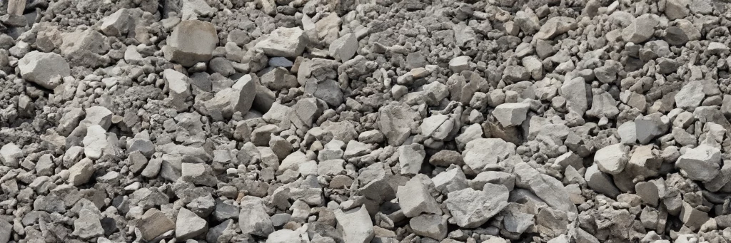
Too coarse for a small box. Stones this size can bridge the plane.
The same geometry sets a hard limit on what can go in the box. When the particles are large relative to the specimen, a handful of stones can bridge the shear plane and the result stops describing the soil and starts describing those stones. Coarse fill, shale, slag, brick rubble and colliery spoil all fall into this category, and the usual laboratory box is simply too small to give an answer anyone should design from.
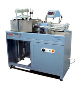
That is the reasoning behind a large machine rather than a preference for bigger equipment. The Shearmatic 300 takes samples up to 300 mm square, reducible to 150 mm with an insert, and carries 100 kN in both shear and consolidation. A sample that size gives a more representative indication of strength in material that is not uniform, and it is the practical way to measure the angle of friction between two different materials rather than within one. Our equipment overview of soil shear strength testing covers that machine in detail.
What the plane is averaging
The Box Decides How Much Material Gets a Vote
Both squares are the shear plane seen from above, drawn to the same scale, and both carry the same particles at the same density. On the small plane a single coarse particle is a noticeable share of the area, and a few of them lying together can bridge it, so the number that comes out describes those particles rather than the fill. On the large plane the same particle is a detail. The strength a shear box reports is an average over that area, which is why the box size is a measurement decision and not a convenience.
Scroll the diagram sideways to see all of it.
Normal Stress Has to Stay Where You Put It
The normal stress is the independent variable of the whole test. Shear strength is reported as a function of it, which means a normal stress that drifts during shearing quietly corrupts the axis everything else is plotted against.
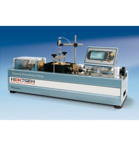
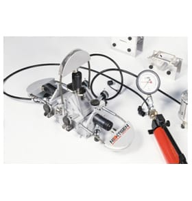
Drift is not hypothetical. A dense soil or a rough rock joint dilates as it shears, pushing the loading system upward. If that system is stiff and passive, the vertical stress rises with the dilation and the specimen is sheared under a condition nobody specified. The Rock Shear Box answers this with an adjustable low friction pressure maintainer on the normal loading system, which absorbs the volume change of the specimen while shearing is under way and holds the vertical stress constant instead of letting it climb. The apparatus was developed at Imperial College by Professor E. Hoek, and it remains the classic arrangement for a reversible shear test on a rock discontinuity.
The axis everything is plotted against
A Dilating Specimen Pushes Back on the Loading System
A dense soil or a rough joint does not simply slide, it rides up, and the loading system above it has to give way by exactly that amount or the normal stress changes. A stiff passive system resists the lift and the stress climbs, so the strength is recorded against a normal stress that was never specified and is not the one written in the report. A low friction pressure maintainer takes up the volume change and leaves the stress where the programme put it.
Scroll the diagram sideways to see all of it.
On the soil side the same problem used to be solved with dead weights, with all the handling that implies. The Shearmatic replaces them with a pneumatic closed loop through a high performance regulator, with the microprocessor reading force, axial pressure and displacement and managing the motor, the pressure valve and the test steps together. Removing the weights is what turns a consolidation and shear sequence into a run that can proceed unattended through up to fifty consolidation steps, and it removes the operator from the one part of the test where a mistake is invisible afterwards.
Three Tests That Share a Frame and Answer Different Questions
Direct shear is not one test. The specimen type decides what the shear plane represents, and with it the standard, the boundary condition and how the result should be read.
One frame, three questions
What the Shear Plane Actually Represents
The frame does not change between these three tests. What changes is what the plane means. In soil the plane is imposed by the apparatus, which is the method’s convenience and its limitation at the same time. In rock the plane is a real discontinuity, and the question is whether it slides rather than how strong the rock substance is. At an interface the plane belongs to neither material, and the strength that governs the design lives on the contact between them.
Scroll the diagram sideways to see all of it.
Soil, Sheared Drained
The routine case is a consolidated drained test on soil under D3080. The specimen is consolidated under a selected normal stress, then sheared slowly enough that excess pore pressure does not build, and the sequence is repeated at other normal stresses so a drained strength envelope can be fitted. The short drainage path in a shear box is a genuine practical advantage here, since it lets the drained condition be reached in a reasonable time. The cost is the one already named: a fixed plane, non-uniform stress on it, and an area that reduces as the halves displace.
The drained sequence
Why One Run Is Never the Answer
A direct shear programme produces points. The engineering value is in the envelope fitted through them, which is why the standard treats several normal stresses as part of the method rather than as extra work.
1
Choose the stresses
Normal stress levels are picked to bracket what the ground will actually see, because an envelope extrapolated past them is an opinion.
Before the first specimen
2
Consolidate
The specimen is consolidated under the selected normal stress, in staged steps where the programme calls for them.
Up to 50 steps
3
Shear slowly
Slow enough that excess pore pressure does not build. The short drainage path in a shear box is what makes that practical on a schedule.
Drained condition
4
Repeat
The same sequence at the other normal stresses, with the normal stress held where it was set while the specimen dilates.
One point each
5
Fit and report
A strength envelope through the points, with the stress range it was fitted over stated alongside it.
The deliverable
Residual strength deserves the same discipline. A joint or a clay that has already displaced does not recover its peak strength, so a design relying on peak values where movement has occurred is reading the wrong part of the curve.
Rock, at Constant Normal Force
Rock work under ASTM D5607 is run at constant normal force, on intact specimens or on specimens containing a single discontinuity, which may be open, healed or filled. The question is almost never the strength of the rock substance. It is whether a joint will slide, and at what normal stress, which is why the method is written around peak and post-peak behaviour rather than a single strength number. ASTM has marked this method withdrawn, so when it appears in a specification it is worth confirming with the client which edition and boundary condition they expect before the first specimen is cast.
Interfaces, Where Two Materials Meet
The third case is the one that catches people out, because the shear plane is not inside the material at all. Geosynthetic liners against soil, and concrete poured against rock, both fail at an interface, and the strength that governs the design belongs to that contact rather than to either material on its own. The Shearmatic 300 is declared to ASTM D5321 and EN ISO 12957 alongside D3080 for exactly this work, and the large sample matters more here than anywhere else, because an interface is only as representative as the area you test.
What the Frame Has to Do While Nobody Is Watching
A drained shear test is slow by design, and a residual test is slower still. That puts the burden on the frame and its measurement chain rather than on the operator, because most of the test happens with the laboratory empty.
Where the horizontal force is applied turns out to matter as much as how much of it there is. On the Shearmatic 300 the shear box, the drive unit and the load cell are connected in line, so the force is transmitted axially along the shearing plane, in place of the classic swan neck arrangement. A load path that has to turn a corner introduces a moment that the shear plane never asked for, and on a large, stiff specimen that moment is not trivial.
Speed control is the other half. That machine drives steplessly from zero to 11 mm per minute, which covers both a drained rate slow enough to keep pore pressure from building and the faster passes used to develop residual strength after the peak has gone. Consolidation is handled in the same sequence, with pre-set steps applied hydraulically, so a staged programme runs without anyone returning to the bench between stages.
Shearmatic. Load cell and transducers come with it.
The instrumentation has to be worth the wait. The Shearmatic arrives with its measurement chain complete: a bi-directional load cell of 5 kN with a nominal sensitivity of 2 mV/V, displacement transducers of 10 mm and 25 mm travel with 0.002 mm repeatability, and a pressure transducer reading to 0.1 kPa. On the rock side the two versions of the shear box differ in precisely this respect, one reading from five digital gauges of 25 mm at one micron resolution, four vertical and one horizontal, the other taking the same movements through potentiometric transducers into an external logger. Four vertical readings rather than one is a deliberate choice, because a rough joint does not lift evenly, and a single dial can indicate a clean vertical displacement that the specimen never made.
One practical note that catches first-time buyers: shear box assemblies are selected and ordered separately from the machine, since the box is sized to the specimen rather than to the frame.
Two ends of the same method
A Large Plane for Soil, a Held Stress for Rock
The frame is chosen by what the plane has to represent. One machine exists because the material will not fit a laboratory box, the other because a dilating joint will not hold its normal stress on its own.
Large box, soil and interfaces
Shearmatic 300
Samples up to 300 mm square, reducible to 150 mm with an insert, with the box, the drive and the load cell in line so the force runs axially along the shearing plane instead of around a swan neck.
Coarse fill, shale, slag, colliery spoil, geosynthetic interfaces100 kN in shear and consolidation, speed 0 to 11 mm/min, up to 50 consolidation steps
The Imperial College arrangement developed by Professor E. Hoek, with an adjustable low friction pressure maintainer that absorbs the volume change of a dilating joint so the vertical stress does not climb during shearing.
Intact rock, or a single joint that may be open, healed or filledSamples to 115 by 125 mm or cores to 102 mm, gauge range 50 kN
A direct shear programme produces points, and the engineering value comes from the envelope fitted through them rather than from any single run. That is why the standard treats multiple normal stresses as part of the method rather than as extra work, and why normal stress levels are chosen to bracket what the ground will actually see. A strength envelope extrapolated well beyond the stresses that were tested is an opinion, not a measurement.
Residual strength deserves the same discipline. A joint or a clay that has already displaced does not recover its peak strength, and a design that relies on peak values where movement has already occurred is reading the wrong part of the curve. Machines built for this work allow the shear to be reversed or run at different speeds so peak and residual can both be captured in one setup.
The last thing worth saying is that the apparatus does not decide whether the method was right. Direct shear is chosen when a defined plane is wanted or when the drained condition has to be reached on a practical schedule. Where the stress path matters, or where a full stress and strain relationship is needed, the answer lies with triaxial testing instead, and the honest version of a shear box report says which question it was built to answer.
Talk to us about shear testing
Tell Us the Material and the Plane You Care About
What the material is, how large the coarsest particle in it gets, the normal stress range the design has to cover, and whether the plane of interest sits inside the material or at a contact between two of them. That is enough for us to say which box size, which loading system and which instrumentation suit the programme, and how much of it can run unattended.
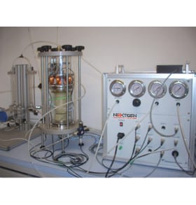 Soil Mechanics TestingResonant Column and Torsional Shear TesterThe Resonant Column and Torsional Shear Tester combines RC and TSS testing in one system for evaluating small-strain soil behavior. It measures shear wave velocity,...View product
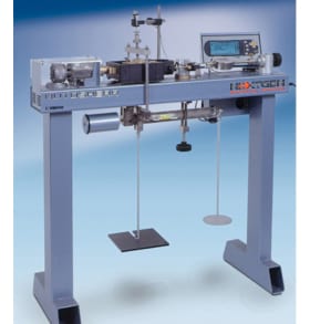 Soil Mechanics TestingAutomatic Shear Testing MachineThe Automatic Shear Testing Machine, also known as NG-Shear DGEN, is built for direct shear testing of soil under consolidated drained conditions. It automates test...View product
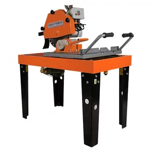 Rock Mechanics TestingRock Core Cutter and Masonry SawThe Rock Core Cutter and Masonry Saw is a universal cutting system for concrete, rock cores, and irregular rock samples. Available with 450 mm or 600 mm blade...View product
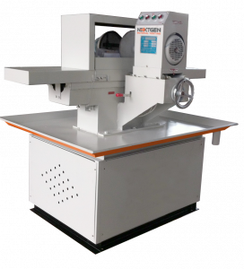 Rock Mechanics TestingNG-CoreGrind 2000 – Double-Faced Rock Core GrinderNG-CoreGrind 2000 is a double-faced rock core grinder for preparing flat, parallel specimen ends before rock mechanics and concrete testing. It is built to grind...View product
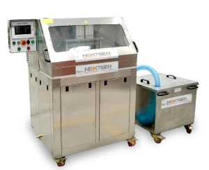 Rock Mechanics TestingCoreGrind 3000 – Automatic Core Grinding MachineCoreGrind 3000 is a fully automatic core grinding machine for preparing rock core specimens before geotechnical and rock mechanics testing. It uses a 7-inch...View product
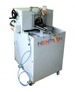 Rock Mechanics TestingNG-CoreGrind 1000 – Semi-Automatic Core Grinding MachineNG-CoreGrind 1000 is a semi-automatic core grinding machine for preparing rock and concrete specimens as an alternative to traditional rubber or sulfur capping....View product
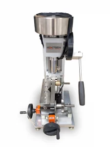 Rock Mechanics TestingWest Cerchar Abrasivity Index TesterThe West Cerchar Abrasivity Index Tester measures rock abrasivity for mining, tunneling, and underground construction applications. Built around ASTM D7625-10, it...View product
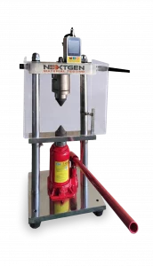 Rock Mechanics TestingPortable Point Load TesterThe Point Load Tester is a portable rock strength testing system for fast field and laboratory assessment of core samples and irregular rock fragments. It...View product
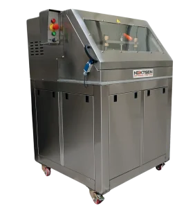 Rock Mechanics TestingCoreTrim 3000 – Core Cutting MachineCoreTrim 3000 is a fully automatic core cutting machine for preparing cylindrical rock specimens before laboratory testing. It cuts cores from 38 to 100 mm...View product