Melt flow rate is the first property on most thermoplastic datasheets and the figure a molder checks when a new resin lot arrives. It is also easy to argue about: two laboratories test pellets from the same bag on two calibrated instruments and report numbers further apart than the specification allows. The test is simple, but sensitive to details the result does not show, such as the melt temperature just above the die, moisture in the pellets and how the charge was packed.
This guide follows ASTM D1238 and ISO 1133 in the order a laboratory meets them: the number, the conditions, Procedures A and B, MFR against MVR, the differences between the standards, and why results drift.
What a Melt Flow Rate Measures
The standards call the instrument an extrusion plastometer; most laboratories call it a melt flow indexer, melt indexer or melt flow index tester. It is a heated vertical cylinder with a short die at the bottom and a piston that carries a dead load. Under ISO 1133-1 the cylinder bore is 9.550 ± 0.007 mm, and the die is 8.000 ± 0.025 mm long with a 2.095 mm bore held within 0.005 mm. A few grams of pellets, powder or flake melt in the bore, and the piston pushes them out through the die.
The result comes in two forms. Melt mass-flow rate, MFR, is the mass extruded, scaled to 10 minutes and given in g/10 min, which ISO also writes as dg/min with the same number. Melt volume-flow rate, MVR, is the same rate as a volume, in cm³/10 min. Melt flow index (MFI) and melt index (MI) are older names for MFR that are still in everyday use, including on our own pages. A higher number means an easier flowing melt, which at a given condition means a lower viscosity.
The arithmetic is short: a segment of m grams extruded in t seconds gives MFR = m × 600 / t, since 10 minutes are 600 seconds. NIST’s timed segments in its polyethylene certification runs weighed about 500 mg and were cut one minute apart. On our arithmetic that is 5.0 g/10 min, close to the 5.04 ± 0.20 g/10 min NIST certifies for reference material SRM 1474c at 190 °C and 2.16 kg. The load in that condition is the piston plus its weights, expressed as a mass. NIST’s piston assembly weighed about 100 g and its added weight 2059.8 g, while on our Melt Flow Indexer the piston rod alone is 325 g.
The piston head is 9.474 ± 0.007 mm across and 6.35 ± 0.10 mm long, about 0.08 mm of clearance on the diameter by our arithmetic. ISO 1133-1 asks for bores of at least 500 HV finished below Ra 0.25 µm, and a piston guide, since excessive wear and erratic results are signs of misalignment.
Test Conditions Come From the Material Standard
A melt flow rate without its condition is not a result. Every value belongs to a temperature and a load, written as a pair such as 190/2.16, the standard polyethylene condition of 190 °C and 2.16 kg. ISO 1133-1 says the conditions are normally set by the material standard, with those in common use listed in its Annex A. ASTM D1238 adds that many material specifications call for the method with procedural changes, which then take precedence. The resin specification picks the condition, not the operator.
Pairs commonly quoted from the ISO table include 230/2.16 for polypropylene, 200/5.00 for polystyrene, 220/10.00 for ABS and SAN, 300/1.20 for polycarbonate and 230/3.80 for PMMA. NPL notes that a material class normally has one permitted condition and that polyethylene is the exception, with four loads at 190 °C: 0.325, 2.16, 5.00 and 21.60 kg. Non-rigid PVC compounds have their own extension of the method, ASTM D3364.
Those loads map onto the weights. On our instrument the 325 g piston alone is the 0.325 kg polyethylene load, and pieces of 875, 960, 1640 and 1200 g added in turn give 1.2, 2.16, 3.8 and 5 kg. The optional 10 kg load adds one more 5000 g weight, and 21.6 kg adds three more and one of 1600 g. The weights are made to ±0.5 %, the tolerance on piston plus load that NIST applied under D1238. Even the heaviest condition is gentle: on our calculation, 2.16 kg on a 9.55 mm bore puts about 0.30 MPa on the melt, and 21.6 kg about 3.0 MPa.
Running one material at two conditions gives the flow rate ratio, FRR: the flow rate at one condition divided by the flow rate at the other, usually the higher load over the lower. ASTM’s Procedure D measures it on one charge, and the ratio is commonly read as a sign of how broad the molecular weight distribution is. It does not translate one condition into another; NPL warns that data from different conditions are hard to compare.
Procedure A and Procedure B
Both standards offer two routes from a charge to a result, and the letters line up between them. ISO 1133-1 calls A a mass-measurement method, in which timed cut-offs of extrudate are weighed, and B a displacement method, which records how far the piston moves in a set time or how long it takes to move a set distance.
Procedure A Cuts and Weighs
NIST’s account of certifying its polyethylene reference material is the best free description of Procedure A in practice. The cylinder is stabilised at 190.0 ± 0.1 °C, and the die and piston foot soak in the hot bore for at least 15 minutes before loading. A 5.80 g charge of pellets is packed to keep out air, sized so that the piston stands 46 ± 2 mm above the die when the 7.0 ± 0.5 minute preheat under load ends. The preheat extrudate is discarded, three segments are cut one minute apart, the barrel is purged, and following D1238 only the first timed segment is reported.
D1238 asks for weighing to the nearest 1 mg once the extrudate is cool; NIST weighed to 0.1 mg and timed with a 0.01 s stopwatch, where an error of 0.1 s in 60 s is worth 0.17 %. Our indexer cuts with a small motor at the interval set in the method, or by hand, with 0.01 s timing resolution. A saved method holds the temperature, preheat time, load, interval and number of cuts, and an alarm asks for the weights when the preheat ends.
Procedure B Times the Piston
Procedure B gives MVR, the bore area times the piston travel scaled to 10 minutes, and MFR only when the melt density is known. In ISO 1133-1 the piston carries two marks 30 mm apart, the upper one level with the cylinder top when the piston head is 20 mm above the die, so the measurement runs from 50 to 20 mm. The standard ASTM travel is 25.4 mm, from 46 to 20.6 mm above the die, with a quarter inch travel, 46 to 39.65 mm, for highly viscous materials.
On our indexer the optional encoder rests on the piston rod and reads its travel with 0.003 mm resolution, an error within ±0.02 mm and a 25.5 mm range. The operating manual picks the travel by expected flow, from 3.175 mm for 0.1 to 2 g/10 min up to 25.4 mm for 100 to 400 g/10 min, an ASTM-style list in inch fractions. MVR is calculated at the end of the run, with MFR beside it if the melt density has been entered. ISO 1133-2 prefers the displacement method for sensitive materials, because it can repeat better than cutting and weighing.
ASTM adds two more letters. Procedure C is a timed polyolefin test with a half-height, half-bore die, and its results must not be taken as half of a Procedure B result. Procedure D is the multi-weight test for FRR, not directly comparable with A or B. ISO 1133-1 has its own half-size die, 4.000 mm long with a 1.050 mm bore, allowed above 75 g/10 min or 75 cm³/10 min and noted in the report.
MFR or MVR: Where Melt Density Comes In
MFR equals the melt density times MVR, and ISO 1133-1 allows one to be converted into the other only when the melt density at the test temperature is known. Because the test pressure is low, a value at ambient pressure will do. It is not the density of the pellet on the bench: a room temperature density to ASTM D792 says a good deal about filler content and nothing reliable about the melt.
For filled grades MVR is often the more useful figure. ISO 1133-1 singles it out for comparing materials of different filler content, and NPL explains why: a filler is usually much denser than the polymer, so filler content moves MFR through density alone, while MVR does not depend on density. NPL adds that moulding is volume-controlled, since a cavity has a fixed volume, and that MFR stays the more common figure, probably for historical reasons.
Density is the weak point of any conversion, and NPL lists its uncertainty among the known problems. ISO 1133-2 allows MFR to be calculated from MVR or measured with a cutting device, and our operating manual describes deriving melt density from an extrudate’s mass and the piston travel that produced it. A laboratory reporting MFR from a Procedure B run should state where its density came from, because two densities turn identical piston data into two different results.
ASTM D1238, ISO 1133-1 and ISO 1133-2 Side by Side
The current ASTM edition is D1238-26, active since August 2026, and ASTM notes that D1238 and ISO 1133 cover the same subject but differ in technical content. ISO 1133-1:2022 was a minor revision of the 2011 edition, so adoptions of the 2011 text remain technically the same; JIS K 7210-1 is identical to it. DIN 53735 still appears on old drawings, but it is withdrawn and replaced by DIN EN ISO 1133.
At the bench, D1238 preheats for 7.0 ± 0.5 minutes, while ISO 1133-1 sets its own melting time, which published comparisons list among the differences, and the measuring zones differ too. A method file cannot simply be relabelled from one standard to the other, and a result should name the standard it was run to.
The largest difference is that ASTM has no counterpart to ISO 1133-2, written for thermoplastics sensitive to their time and temperature history in the test or to moisture: grades of PET, PBT, PEN and polyamides affected by hydrolysis, and TPE and TPV affected by cross-linking. It holds the cylinder within ±1 °C absolute and ±0.3 °C relative from 0 to 70 mm above the die, and tightens the time line, the sample amount and the pre-treatment. Moisture content is determined to ISO 15512, vacuum ovens are preferred, and dried material goes into a dry, preferably hot container and is tested within 4 hours, or within 2 days from a desiccator. ISO 1133-2:2011 was confirmed in 2021 and is under review again.
Why Melt Flow Results Drift
ASTM D1238 warns that small, hard-to-spot variations in technique, geometry or conditions cause discrepancies, and carries a troubleshooting appendix for them. Industry’s complaints to NPL included poor repeatability between operators, samples too small for the batch and fillers blocking the die.
Temperature at the Die
Temperature is the largest variable a laboratory controls. For polyethylene near 190 °C, NIST measured a change of about 1.65 % in MFR per degree, and for its current reference material a 0.2 °C uncertainty is worth 0.016 g/10 min on 5.04 g/10 min. NPL measured MVR changes of 1 to 2 % per degree for polypropylene, about 3 % for PBT and about 5 % for PET.
Where the temperature is read matters as much as the setpoint. NIST found the melt within 0.1 °C of setpoint from 12 mm above the die upward, but 0.7 °C lower at 1 mm. ISO 1133-1 notes that the wall sensor may not read the melt, and allows the control to be calibrated in the melt. NPL estimated that flow through the die warms the melt by about 0.15 °C at 2.16 kg but about 1.5 °C at 21.6 kg. Our indexer sets temperature in 0.1 °C steps and holds within ±0.5 °C over four hours.
Moisture, Drying and Degradation
Hydrolysis lowers molar mass and melt viscosity, so moisture raises MFR and MVR. In NPL’s PET work, pellets dried for 3 hours gave an MVR about 45 % higher than pellets dried for 5 hours at 130 °C, and 4 hours gave about 20 % higher. Three back-to-back tests from one sealed jar of dried pellets climbed 18 %, from 10.12 to 11.91 cm³/10 min, as the pellets took up moisture. PBT left 24 hours in laboratory air flowed about 15 % faster, while PA66 fell slightly, possibly from further polymerisation after over-drying, so the error runs both ways.
NPL found one standard deviation of about 2 % for polypropylene and up to about 10 % for PET, and proposed a check rather than a rule: if MFR moves by more than about ±10 % when the drying time is doubled or the temperature shifts by 2 °C, the method does not suit that material. Degradation also raises flow by lowering molecular weight. Laboratories use that to compare a moulded part with its resin, and since time in the barrel can degrade a sample on its own, ISO 1133-2 limits the time at temperature.
Packing, Cleaning and the Instrument
NPL traced early transients in high-flow materials to trapped air and poor packing, made worse because the melt leaks through the die before it can be compacted. NIST packed its pellets to keep out air, and ISO 1133-1 describes preforming powder or flake into a compacted charge. Our indexer has a funnel-shaped barrel mouth, a compressing rod in the tooling and a red-handled die plug that closes the die outlet while a high-flow sample is charged.
NIST cleaned the bore after every run with cotton gun cloth and the die and piston with a brass brush, avoided steel tools, and accepted a bore as clean when the die dropped through it freely. ISO 1133-1 discards a die that the no-go gauge enters at all, or one that is chipped, and a die worn oversize reads high. NIST’s level check found at most 0.14 degrees of tilt, worth only 3 × 10⁻⁴ % of the load, so tilt matters through friction on the piston. Our manual lists an unlevel machine and worn dead weights among the causes of scattered results.
- Condition and procedure match the material standard, and the report names both.
- Melt temperature verified near the die, not only at the wall sensor.
- Moisture-sensitive pellets dried and tested within the time ISO 1133-2 allows.
- Charge packed without trapped air, preheat timed to the method.
- Die checked with the go/no-go gauge, bore cleaned with brass or cotton, machine level.
What the Number Tells a QC Laboratory
Both standards treat melt flow as a quality control test. ASTM D1238 describes the flow rate as an empirical value showing how uniform a polymer is as made, not a fundamental property. ISO 1133-1 adds that shear rates in the test are much lower than in processing. On our calculation they are about 1.8 s⁻¹ at an MVR of 1 cm³/10 min, 18 s⁻¹ at 10 and 185 s⁻¹ at 100, while processing rates can exceed 1000 s⁻¹.
NPL draws the consequence: rankings at low shear rate may differ from rankings at high shear rate, and equal melt flow does not mean equal processing. Used within those limits, melt flow tells a laboratory whether a lot matches the last one, gives an indirect read of molecular weight, and shows degradation when a moulded part is compared with its resin.
The spread between laboratories deserves a number. On SRM 1474a, NIST measured a single-laboratory standard deviation of 0.056 g/10 min over 45 runs, against an estimated 0.20 g/10 min between instruments in different laboratories, four times larger. For SRM 1474c the lab-to-lab term from the D1238 round robin dominates the uncertainty, while weighing and timing are negligible. A certified reference material such as NIST SRM 1474c is the direct check on a polyethylene method, and NPL Report MAT 3 covers moisture-sensitive materials in depth.
Melt flow is rarely the only test on a resin lot. Behaviour under heat and load is covered in our guide to HDT and Vicat softening temperatures, and mechanical properties in choosing a universal testing machine for plastics.
Our Melt Flow Indexer is built around the ISO 1133-1 geometry, a 9.550 ± 0.007 mm cylinder and a nitrided standard die of 2.095 ± 0.005 mm by 8 ± 0.025 mm, with a single-body red-copper oven, a self-guided 325 g piston rod and a 7 inch touch screen with a micro-printer. The encoder, the 10 kg and 21.6 kg loads and the narrower dies are ordered by method. The melt flow testing equipment page lists the full specification, and our earlier product overview walks through the instrument feature by feature.
Keep Reading in Melt Flow Testing Equipment for Plastics
See the Melt Flow Testing Equipment for Plastics rangeMachines Behind This Article
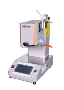 Melt Flow Testing Equipment for PlasticsMelt Flow IndexerThe Melt Flow Indexer measures melt flow rate, melt index, and melt volume rate of thermoplastic materials for quality control, research, and material development....View product
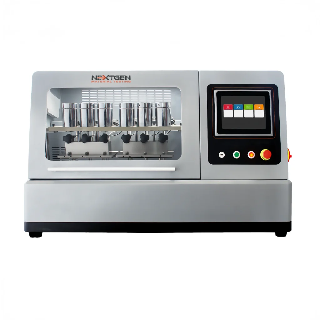
 Plastic TestingNG-HDT – HDT/Vicat Testing Machine for PlasticsNG-HDT is an HDT/Vicat testing machine for measuring heat deflection temperature and Vicat softening temperature of thermoplastics, including pipes and fittings....View product