An Izod value is often the first impact number on a plastics datasheet, and it is easy to read more into it than it holds. A notched bar is clamped upright, a pendulum swings once, and the energy it lost breaking the bar becomes a single figure in J/m or kJ/m². Behind that figure sit a choice of standard, a notch cut a particular way, a hammer of a particular size and a break that may not have been complete. Change any of them and the number moves, sometimes far enough to reverse the ranking of two materials, which ASTM D256 itself warns can happen.
This guide follows the test the way a plastics laboratory meets it: how the bar is loaded, what the current ASTM D256 contains, the specimens and notches of D256 and ISO 180, where the pendulum’s energy goes, how the break is classified, and why J/m and kJ/m² results cannot be set side by side. Our introductions to Charpy and Izod impact tests and to plastic impact testing and sample preparation cover the basics.
How the Izod Test Loads a Specimen
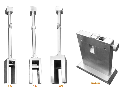
In an Izod test the specimen stands vertical, held at its lower end in a vise, and is struck once by a pendulum at a fixed distance above the jaws. ISO 180 describes it as a vertical cantilever beam broken by a single impact, with the line of impact a fixed distance from the clamp and from the notch centerline. The notch sits level with the top of the vise and faces the striker: the ISO definition of notched Izod impact strength specifies that the pendulum strikes the face containing the notch. The pendulum keeps swinging after the break, and the energy it no longer has is what the test records.
The notch makes the test repeatable. ASTM D256 explains that it concentrates stress, keeps plastic deformation small and directs the fracture into the section behind the notch, which reduces scatter, and that it makes a brittle fracture more likely than a ductile one. The standard adds a caution that runs through the rest of this guide: different materials respond to the same notch differently, because their elastic and viscoelastic behavior differs.
The machine is standardized too. D256 describes testers built around a fixed height of hammer fall, giving an essentially fixed velocity at impact, with hammers of different initial energies for specimens of different toughness. Makers choose their own pendulum length and construction, so pendulum rigidity differs between designs. ISO 180 refers machine verification to ISO 13802, whose 2025 edition covers pendulum machines for Charpy, Izod and tensile impact on plastics when they are installed, repaired, moved or periodically checked.
What comes out is a comparative number. D256 places its value mainly in quality control and materials specification and warns that a ratio of toughness under these conditions need not hold under others. ISO 180 states that its method is not intended as a source of data for design calculations. An Izod result tells a laboratory whether a batch behaves like the reference. It does not predict how a molded part will survive a drop.
ASTM D256 Today: Test Methods A and C
The active edition is ASTM D256-26, last updated in April 2026, and its scope lists two test methods. Test Method A is the cantilever beam test. Test Method C is the same test for materials with an Izod impact resistance below 27 J/m (0.5 ft·lbf/in.), and D256 requires Method C for those materials. Both use a milled notch and report the energy absorbed per unit of specimen width or, as an optional unit, per unit of cross-sectional area under the notch. Where the material specification sets preparation, conditioning, dimensions or test parameters, it takes precedence, and the defaults in D256 only fill the gaps.
Method C exists because of toss. When a brittle bar breaks, its free end is thrown, and the energy spent throwing it is counted as if the specimen had absorbed it. For brittle materials, D256 explains, the indicated energy is practically the energy to start the fracture plus the toss energy, and for dense brittle materials the toss correction can be a very large fraction of the total. Method C estimates the toss energy and corrects for it, and the standard is candid that the correction is an approximation: the re-toss velocity may differ from the original, and stresses stored in the specimen may be released.
Many specifications and web pages still refer to Test Methods D and E. They were in D256 up to the D256-23e1 edition and were gone by D256-24. Method D measured notch sensitivity by comparing the energy to break specimens with different radii at the base of the notch. Method E reversed the notched specimen 180 degrees in the vise, so the pendulum struck the face opposite the notch. Method B, the Charpy configuration, had left D256 earlier; Charpy testing of plastics is now ASTM D6110. Unnotched cantilever beam testing has its own standard, ASTM D4812, although datasheets often cite unnotched values as D256.
A purchase order that asks for “D256 Method E” therefore needs a question back before a specimen is cut: which edition does the specification cite, and does the customer want unnotched data to D4812, a comparison of notch radii, or a standard Method A result? Our ASTM D256 page makes the same point: the method letter comes from the purchaser’s specification.
Specimens and Notches
D256 standardizes its specimens by one fixed length, one fixed depth and one design of milled notch, while letting the width vary between limits. ISO 180 works from a smaller bar and two notch types. The two bars look alike on the bench and differ in nearly every dimension that matters.
Two Bars That Only Look Alike
The D256 bar is commonly described as 63.5 mm long and 12.7 mm deep, and the D256 sizes our Class J lists include 63.5 x 12.7 x 12.7 mm and 63.5 x 12.7 x 6.4 mm. About 10.16 mm is commonly given as remaining under the notch, so the notch is about 2.54 mm deep. The ISO 180 bar is 80 x 10 x 4 mm, the multipurpose bar with its end tabs cut off; ISO 180 fixes the width at 10 ± 0.2 mm with 8 ± 0.2 mm remaining at the base of the notch, so its notch is 2 mm deep, and the usual configuration strikes the bar edgewise. On our Class J the striker meets both 22 mm above the vise, and the two results are then normalized in different ways.
Width is the dimension D256 watches most closely. Some materials behave as ductile below a critical width and brittle above it, so D256 requires the width to be stated in the material specification and reported with the result, and advises against comparing specimens whose widths differ by more than a few mils. ISO 180 asks for micrometers accurate to 0.02 mm and, at the notch, an anvil 2 to 3 mm wide with a profile that fits it.
How the bar was made travels with it. ISO 180 specimens may be molded to size or machined from multipurpose specimens, moldings, laminates or sheet, and D256 lists fabrication method, molding conditions, mold design and thermal treatment among the variables that move results. ISO 180 is not normally used for rigid cellular materials, and notched specimens are not normally used for long-fiber-reinforced composites.
Notch Radius and Notch Quality
ISO 180 has two notch types: type A with a root radius of 0.25 ± 0.05 mm and type B with 1 ± 0.05 mm. A third radius, type C at 0.10 ± 0.02 mm, appears in some summaries of ISO 180, but it belongs to the Charpy standard ISO 179-1. The D256 notch is commonly described with the same 0.25 mm radius and a 45 degree included angle. A sharper root concentrates stress more and a larger radius generally reads higher, which is why the notch type belongs in the result and why a worn knife can shift results while the method stays the same.
D256 names the notching method, the speed of the notching tool, the design of the notching apparatus, the quality of the notch and the time between notching and testing as variables that can affect results significantly. The 2000 edition of ISO 180 added that molded-in notches do not give results comparable with machined ones and that the notch profile is checked at regular intervals.
Instrument makers add guidance on the cutting itself. No chart gives the correct cutter speed for each material, so speed and feed are set by trial, and high speed with slow feed and no coolant does more thermal damage to the notch than the reverse. Makers commonly suggest checking the knife profile after about 500 notches. Our article on why notch verification is required was written around metals specimens, but its reasoning carries over: a notch is measured, not assumed.
Where the Pendulum’s Energy Goes
The tester reads one number, the energy the pendulum lost, and D256 lists nine places it can go: starting the fracture, propagating it, throwing the free end, bending the specimen, pendulum arm vibration, frame or base vibration and movement, bearing and indicator friction plus windage, indentation at the line of impact, and striker friction on the bent specimen. Only the first two are the property the test sets out to measure.
Brittle, Tough and Soft Specimens
Which losses matter depends on the material. For brittle specimens the reading is practically initiation plus toss, which is where Method C comes in. For tough, ductile, fiber-filled or cloth-laminated materials, propagation, arm vibration and striker friction can become significant even with good machining and adequate capacity, and for soft materials bending and indentation can be appreciable. D256 notes that frame losses are small in a rigid, massive machine, while vibration losses can be quite large when wide, tough specimens are tested on a light machine not securely fastened to a heavy base. The center of percussion has to sit at the center of strike to keep arm vibration down.
Two further notes matter when machines are compared. Pendulums that record force with a load cell may not give results equivalent to testers that measure the energy remaining in the pendulum. And manual and digital testers have shown a documented discrepancy, mainly on thermosets including phenolics below 54 J/m (1 ft·lbf/in.), with digital data possibly significantly lower, so D256 suggests a correlation study may be needed.
Choosing the Pendulum
On our Class J the D256 pendulum set is 2.7, 5.4, 10.8 and 21.6 J (2, 4, 8 and 16 ft·lbf) and the ISO 180 set is 2.75, 5.5, 11 and 22 J, all with the center of percussion 335 mm from the axis. Released at 145.2 degrees for D256, the striker falls 610 mm and arrives at 3.46 m/s; released at 150 degrees for ISO 180, it falls about 625 mm and arrives at 3.5 m/s. The drop height usually quoted for D256 follows directly from that geometry.
Laboratories use the lightest hammer that breaks the specimens, so the absorbed energy is a meaningful share of what the hammer carries. Instrument makers commonly quote an upper limit of 85 % of capacity for D256 work and a band of 10 to 80 % for ISO 180; the limits to apply are those of the edition your laboratory reports to. Because pendulum ranges overlap, one absorbed energy can often be reached with two hammers, which is why we recommend fewer than five pendulums per machine: more of them complicate calibration without adding useful range.
Classifying the Break and Reporting the Number
An Izod value is incomplete without the type of break, and D256-26 asks for one of four codes for each specimen. C, complete break, means the specimen separated into two or more pieces. H, hinge break, is an incomplete break in which one part cannot support itself above the horizontal when the other is held vertically. P, partial break, is an incomplete break that is not a hinge but has fractured at least 90 % of the distance from the notch vertex to the opposite side. NB, non-break, means the fracture extends less than 90 % of that distance.
Results from different failure types are not directly comparable, so an average is calculated within one category and carries its letter code. Where a set breaks in mixed ways, D256 asks for the average of each type with the percentage of specimens that failed that way, and a non-break is a departure from the standard, not a standard result. ASTM D4812, the unnotched test, uses only C, P and NB and reports a non-break with no number, and ISO 180 has its own break definitions and reporting rules.
Conditioning completes the report. ASTM D618 notes that, depending on thickness, material and history, substantial equilibrium at normal conditions can take 20 to 100 days or more, which is why specifications rely on conditioning for reproducibility. ISO 180 refers to ISO 291 for its atmospheres, and D618 notes that the two conditioning standards differ in technical content. Impact values generally fall as temperature drops, and testing laboratories point out that neither ASTM nor ISO sets the conditioning time for low-temperature work or the time from the cold chamber to impact, so both belong in the report. Our guide to choosing an impact specimen cooling chamber covers that side of the work.
Izod vs Charpy, and ASTM vs ISO
Charpy turns the Izod set-up on its side. ISO 179-1 supports the specimen near its ends as a horizontal beam and strikes it once midway between the supports, directly opposite a single edgewise notch, so the notch faces away from the striker. In Izod the notch faces the striker and the specimen is clamped, and the clamp is the difference most laboratories notice. ISO 180 says some plastics are sensitive to clamping pressure; for them the clamping force has to be standardized, with a calibrated torque wrench or a pneumatic or hydraulic device on the vise screw, and recorded. A Charpy specimen lies free on its supports.
ISO 179-1 describes Charpy as having a greater range of applicability than ISO 180 and as more suitable for materials showing interlaminar shear fracture or surface effects from environmental factors. In ASTM practice, Charpy for plastics is D6110, which requires a complete break and states that no procedure has been established for estimating toss energy. Our Class J runs both configurations, with Charpy pendulums from 1 to 50 J alongside the Izod sets.
Comparing ASTM and ISO Izod results is the more common mistake, because the names match. ASTM D256 says it resembles ISO 180 in title only and that the contents are significantly different. Bars, notch depths, striking conditions, break rules and conditioning standards all differ, and the result is normalized differently. D256 divides the energy by the specimen width and reports J/m or ft·lbf/in., where 1 ft·lbf/in. equals 53.38 J/m. ISO 180 divides it by the thickness times the remaining width at the notch and reports kJ/m², so on a 4 mm bar with 8 mm under the notch every joule absorbed is 31.25 kJ/m².
The optional D256 area unit, energy divided by the cross section under the notch, is not an ISO value either. It is still a number from the ASTM bar, notch and striking conditions, expressed in ISO units, and datasheet conversion factors carry the same flaw. When a specification is written in kJ/m² and the reference data are in J/m, test to the method the specification names.
Izod Testing Equipment from NextGen
An Izod laboratory for plastics needs a pendulum tester with the Izod sets its standards call for and a notching machine that cuts the notches those standards specify. Both sit in our plastic impact testing equipment category.
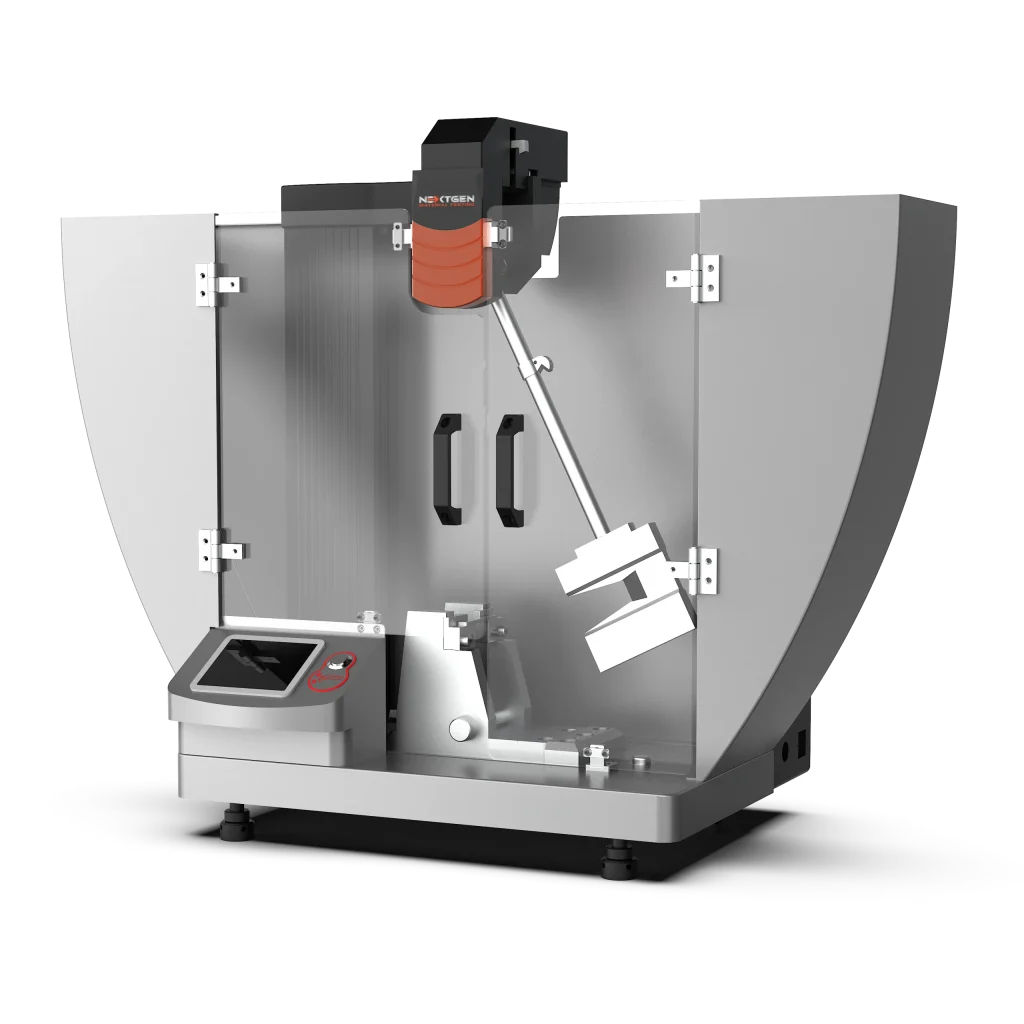
The Class J automatic Charpy and Izod impact tester runs Izod and Charpy on plastics and rubber and, with the tensile impact pendulum, film and sheet to ISO 8256 and ASTM D1822. The pendulum head sits on a shaftless angle encoder with 0.045 degree resolution and is released by an electromagnetic hook. The operator enters specimen dimensions, pendulum energy and units on the touch screen, which shows the angle, the absorbed energy and the impact strength. Izod options are the Izod vise jaw, an Izod notch centering block and the ISO 180 and ASTM D256 pendulum sets, and the single-column frame takes low-temperature accessories later.
The GenNotch 3000 notches plastic specimens 20 at a time and processes 60 in about 10 minutes. Its knives are steel above HRC 60, ground to 45° ± 0.2°: type A with a 0.25 mm radius is standard, and types B (1.0 mm) and C (0.1 mm) are optional, covering ISO 180 types A and B, the D256 radius and the ISO 179-1 type C Charpy notch. Knife speed is adjustable from 0 to 90 mm/min, the setting that matters for thermal damage, and length blocks for 63.5 mm and 80 mm bars are included.
Machines Behind This Article
 Plastic Impact TestingClass J – Automatic Charpy and Izod Impact Tester (1–50 J)Class J is an automatic Charpy and Izod impact testing system for low-energy impact evaluation of plastics and related materials. It covers 1–50 J for Charpy tests...View product
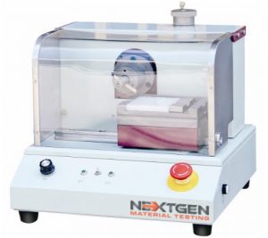 Plastic Impact TestingGenNotch 3000 – Motorized Multi-Specimen Notching and Broaching MachineGenNotch 3000 is a motorized multi-specimen notching and broaching machine for preparing plastic specimens before Charpy and Izod impact testing. It holds up to 20...View product