Precise strain and displacement measurement is fundamental to mechanical and material testing. Whether measuring metal tensile strength or analyzing crack propagation in polymers, the accuracy of extensometers and COD (Crack Opening Displacement) gages plays a critical role in obtaining valid test results. Keeping this level of precision requires adherence to internationally recognized calibration standards.
Among the most important guidelines are ASTM E83 and ISO 9513, which are key standards defining methods for verifying, calibrating, and classifying extensometer systems. These frameworks guarantee that extensometers and COD gages deliver accurate, repeatable, and traceable measurements.
The purpose of this article is to provide a comprehensive analysis of ASTM E83 and ISO 9513. As a result of reading this article, readers will gain a comprehensive understanding of how these standards work, why they are imperative for high-quality measurements, and how compliance supports the integrity of testing procedures.
Overview of Extensometers and COD Gages
First, it is necessary to understand the purpose of extensometers and COD gages, as well as their use in materials testing, before examining the standards in detail.
Extensometers are precision instruments designed to measure the change in the length of a material specimen subjected to mechanical forces such as tension or compression. By capturing the minute deformation that occurs under stress, extensometers allow the calculation of strain, a parameter in 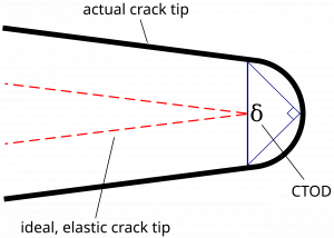 determining material properties, including Young’s modulus, yield strength, and ultimate tensile strength.
The primary purpose of extensometers in material testing is to provide accurate, repeatable strain measurements under controlled conditions. Their use assures that the mechanical characteristics of metals, plastics, composites, and other materials are assessed correctly during standard testing procedures such as tensile, compression, flexural, and fatigue tests.
COD gages (Crack Opening Displacement gages) are specialized types of extensometers engineered specifically to measure the displacement at the tip of a crack during fracture mechanics testing. Unlike general extensometers, COD gages focus on monitoring crack opening under applied loads.
The specific role of COD gages is to provide precise data on crack growth behavior, which is essential for evaluating a material’s resistance to crack propagation, fracture toughness, and overall structural integrity.
ASTM E83: Standard Practice for Verification and Classification of Extensometer Systems
ASTM E83 is a standard that outlines procedures for extensometer verification and classification. It applies to instruments that indicate or record values proportional to length changes corresponding to tensile or compressive strain. The standard applies to extensometers based on either SI or US customary displacement units.
The primary purpose of ASTM E83 is to guarantee that extensometer systems provide accurate and reliable measurements during mechanical testing. Using this standard, testing laboratories can maintain consistency and traceability in their strain measurements, which is crucial for material characterization and quality control.
Extensometer Classification System
ASTM E83 classifies extensometer systems based on their magnitude into several classes, each with specific performance criteria:
-
Class A: Highest accuracy, with a maximum error of ±0.1% strain.
-
Class B-1: High accuracy, with a maximum error of ±0.5% strain.
-
Class B-2: Moderate accuracy, with a maximum error of ±0.5% strain.
-
Class C: Standard accuracy, with a maximum error of ±1% strain.
-
Class D: Lower accuracy, with a maximum error of ±1% strain.
-
Class E: Lowest accuracy, with a maximum error of ±1% strain.
Verification Procedures for Extensometers
Verification of extensometer systems involves applying controlled displacements to a simulated specimen and measuring them accurately. The extensometer’s readings are then compared to known displacements to determine its accuracy. The verification process includes:
-
Calibration: Determining the calibration factor, which is the ratio of change in length to the product of the gauge length and the change in the extensometer reading.
-
Resolution Check: Ensuring that the extensometer’s resolution meets the classification requirements.
-
Error Analysis: Calculating fixed and relative errors to confirm compliance with class limits.
Explanation of Gauge Length Types
ASTM E83 categorizes extensometer systems into three types based on how gauge length is defined:
-
Type 1: Extensometer systems that both define gauge length and sense extension. An example is a clip-on strain gauge with conditioning electronics.
-
Type 2: Extensometers that sense extension, with the gauge length defined by specimen geometry or features such as ridges or notches.
-
Type 3: Extensometer systems that intrinsically sense strain using the ratiometric principle, such as video camera systems.
ISO 9513: Calibration of Extensometer Systems Used in Uniaxial Testing
The next standard in our queue is ISO 9513:2012, an international standard that specifies a method for static calibration of extensometer systems used in uniaxial testing. It applies to both axial and diametral extensometer systems, including both contacting and non-contacting types. This standard defines procedures for verifying that extensometers provide accurate and reliable measurements, such as tensile strength and elasticity, needed for material properties determination.
 Accuracy Classes Defined by ISO 9513
ISO 9513 classifies extensometer systems into accuracy classes based on measurement performance. The classification considers factors such as resolution, relative error, and bias error. The main accuracy classes are:
-
Class 0.5: Highest accuracy, suitable for applications requiring precise strain measurements.
-
Class 1: Standard accuracy, adequate for most general testing purposes.
-
Class 2: Lower accuracy, acceptable for less critical measurements.
Calibration Procedures
ISO 9513 calibration involves comparing extensometer readings to known displacements provided by a calibration apparatus. Key steps include:
-
Pre-Calibration Inspection: Before calibration, the extensometer is inspected for mechanical integrity, including checking for wear or damage.
-
Calibration Setup: The extensometer is mounted on a calibration device capable of applying precise displacements.
-
Measurement Sequence: A series of displacements is applied, and the extensometer’s readings are recorded and compared to known values.
-
Error Analysis: The relative bias error and resolution are calculated to determine the extensometer accuracy class.
Practical Application: Why Calibration According to ASTM E83 and ISO 9513 Matters
Now that we have familiarized ourselves with the standards and their key principles, it is time to move beyond the definitions and understand their practical applications. Accurate calibration of extensometers and COD gages according to ASTM E83 and ISO 9513 is not just a formal requirement; it has a direct and critical influence on material testing reliability, test results, and overall laboratory performance. We will explore why calibration is important and how it impacts real-world testing and quality assurance.
Impact of Accurate Extensometer Calibration on Material Testing Results
Strain measurement directly affects mechanical properties such as yield strength, tensile strength, fracture toughness, and elastic modulus. An extensometer that does not meet calibration standards can distort strain values, causing false interpretations of material behavior.
For example, if an extensometer underestimates strain during a tensile test, the calculated modulus of elasticity will appear artificially high, potentially leading to the incorrect classification of a material’s performance limits. Especially in critical areas, such misjudgments may contribute to premature structural failure, reduced component lifespans, or even catastrophic accidents.
In production environments, inaccurate extensometer readings may cause batches of non-compliant materials to pass acceptance tests, introducing hidden defects into manufactured products. This risk highlights the necessity for regular, traceable calibration in compliance with recognized standards.
How Proper Calibration Improves Testing Reliability and Data Reproducibility
 Consistent calibration guarantees that strain measurements remain stable and comparable over time and across different testing setups. Properly calibrated extensometers produce data that is reproducible within the same laboratory and correlates accurately with results from other accredited laboratories.
For instance, a manufacturer conducting tensile tests in multiple facilities must rely on calibrated extensometers to verify consistent measurements, regardless of where the tests are performed. If calibration is neglected, the variations between devices can exceed acceptable margins, making comparative analysis impossible and invalidating product certifications.
Research environments require reproducibility. Experimental material development programs often involve collaboration between universities, private laboratories, and industrial partners. Extensometers that are not calibrated according to ASTM E83 and ISO 9513 introduce uncontrolled variables into the experiments, undermine the validity of published findings, and delay innovation.
Role of Calibration in Laboratory Quality Assurance Programs
Maintaining calibration records provides traceability, documenting that each device consistently meets specific accuracy classes over time. Traceability ensures confidence in laboratory results during internal audits, external inspections, and client reviews.
Furthermore, calibration supports risk management by reducing the probability of testing errors that could lead to unsafe products. For industries operating under strict regulatory control, such as medical devices, energy, or civil construction, calibration is a necessity not only for technical accuracy but also for legal compliance and market access.
Support for ASTM E83 and ISO 9513 Compliance
If you are seeking calibration services or material testing equipment that complies with ASTM E83 and ISO 9513 standards, it is important to choose solutions that guarantee accurate and traceable strain measurements in tensile, compression, and flexural testing. Full compliance requires not only initial calibration but also regular verification to maintain device performance and measurement reliability over time.
At NextGen Material Testing, we provide comprehensive calibration and verification services for extensometers, COD gages, and related strain measurement devices. Our expertise covers the full range of requirements, including direct verification, linearity assessments, and classification according to ASTM E83 and ISO 9513. We offer calibration for both our systems and third-party equipment, assuring traceability and auditability.
Access to ISO and ASTM-accredited calibration services enables our clients to meet certification requirements in a variety of fields. Whether calibrating axial extensometers, transverse extensometers, COD gages, or deflectometers, we deliver the precision and documentation needed for successful laboratory accreditation and quality assurance programs.
Contact NextGen to secure reliable calibration solutions that uphold the highest industry standards for accuracy, repeatability, and regulatory compliance.
 Flexural (Bend) Testing Explained: 3-Point vs 4-Point, Standards, and SetupFlexural (bend) testing explained: what it measures, three-point vs four-point setups, the standards for plastics, metals, composites and concrete, and how to choose the right fixtures and...Read the articleGenTest Software Setup Guide for NextGen NG-EML Universal Testing MachinesGenTest setup affects the full UTM testing workflow: method storage, PC-to-controller communication, user permissions, simulation files, live data acquisition, and report output. This guide follows the GenTest setup video step by step for NextGen NG-EML electromechanical universal testing machines. It covers installation, license activation, workspace configuration, UTM controller connection, safety and peripheral setup, user management, DEMO Mode, simulation files, Control Panel setup, Quick Test, and test method creation. GenTest is the software layer where the test method, machine connection, operator input, live data, calculated results, and report output come together. For operators, service teams, QA/QC labs, and R&D users, the goal is to...Read the articleBrinell, Rockwell, Vickers, or Microhardness: Which Test Makes Sense for Your Application?Choosing a hardness test starts with the part itself. Material type, section thickness, geometry, surface condition, inspection purpose, and required testing speed all affect which method will produce a reliable result. Brinell, Rockwell, Vickers, and microhardness methods work differently, so they are not equally suitable for the same component or the same quality task. Brinell, Vickers, and Knoop are based on the size of an indentation, while Rockwell is based on indentation depth. That difference directly affects how the result is obtained and where the method fits best. In production and lab work, problems usually appear when the test method does not fit the application. A part may be too thin for the selected load, the surface may be too rough...Read the articleSpecimen Size Effects in Charpy Testing: What Engineers Need to KnowCharpy V-notch testing remains widely used because it offers a standardized and efficient way to evaluate impact behavior in metallic materials. In production, qualification, and failure analysis work, it is often used to compare toughness response across temperatures, material conditions, and product forms. The standard Charpy specimen measures 10 × 10 × 55 mm, but that geometry is not always available in practice. Thin sections, weld zones, heat-affected zones, and limited extraction volumes often make full-size specimens impractical. ISO 148-1 addresses this directly by permitting sub-size specimens when a standard specimen cannot be produced, including reduced-thickness options such as 7.5 mm, 5 mm, and 2.5 mm. That change affects more than the...Read the article
Machines Behind This Article
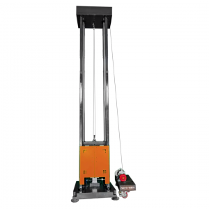 Metal TestingDWT-1800 – Computer-Controlled Drop Weight Impact TesterDWT-1800 is a computer-controlled drop weight impact testing machine for evaluating impact resistance in metal and non-metal materials. Capable of high-energy tests...View product
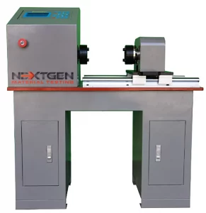 Metal TestingGenTor – Horizontal Torsion TesterNextGen GenTor is a horizontal torsion tester for measuring torque, torsion angle, deformation, and torsional strength in metals and components. With capacity...View product
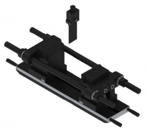 Metal TestingHeavy-Duty Bending Fixtures for Hydraulic Flexural TestingHeavy-duty bending fixtures support high-force flexural testing of metals, composites, ceramics, reinforcing bars, and structural materials on hydraulic universal...View product
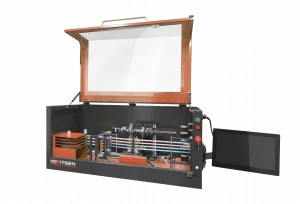 Metal TestingNG-AutoPol – Automatic Longitudinal Polisher for Tensile SpecimensNG-AutoPol is an automatic longitudinal polishing system for metallic tensile and fatigue specimens. It removes machining marks, grinding stress, and residual...View product
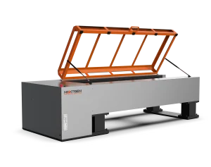 Metal TestingNG-EML Series H – Horizontal Universal Testing MachineNG-EML Series H is a horizontal universal testing machine line for tensile, proof load, elongation, and breaking force testing of long or difficult-to-handle...View product
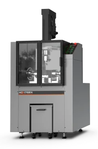 Metal TestingNG-FLX Series A – Flexural and Bend Testing SystemNG-FLX Series A is an electromechanical flexural and bend testing system for controlled sheet metal bending, three-point bend testing, flattening tests, ductility...View product
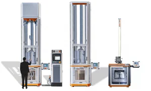 Metal TestingNG-FWT1 and NG-FWT2 – Drop Weight Impact Testers (up to 2000 J)NG-FWT1 and NG-FWT2 are low-capacity vertical drop weight impact testers for controlled falling-weight tests up to 2000 J. They help evaluate impact resistance,...View product
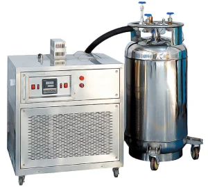 Metal TestingNG-ISCC Series – Impact Specimen Cooling ChamberNG-ISCC Series is a low-temperature chamber for conditioning Charpy impact specimens before pendulum impact testing. Available in -60°C, -80°C, -100°C, and -196°C...View product
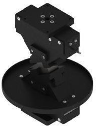 Metal TestingSplitting Fixtures for Rock and Concrete TestingSplitting fixtures for indirect tensile testing are designed for rock, concrete, and composite specimens tested on hydraulic universal testing machines. Built for...View product