
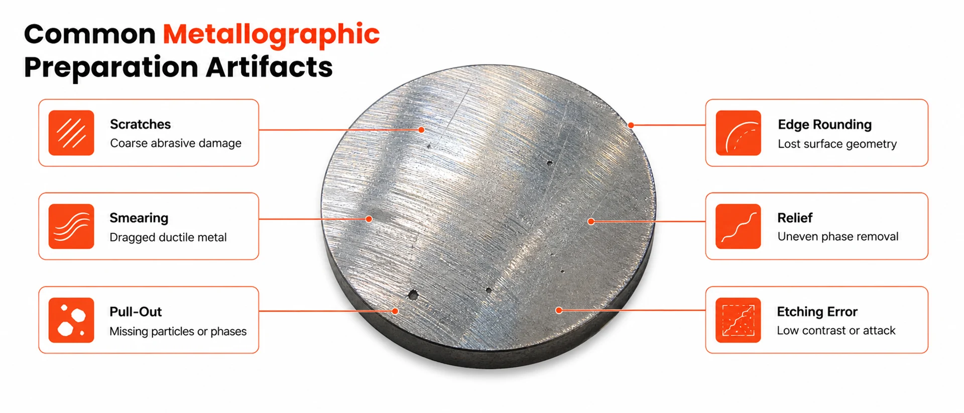
Metallographic preparation artifacts often appear in the same areas engineers need to evaluate most carefully: pores, inclusions, coating interfaces, grain boundaries, heat-affected zones, and surface-treated layers.
A scratch can cross the same area as a suspected crack. Pull-out can look like porosity. Edge rounding can distort a coating or case-depth measurement. Smearing can cover fine features in a ductile alloy before the sample reaches final inspection.
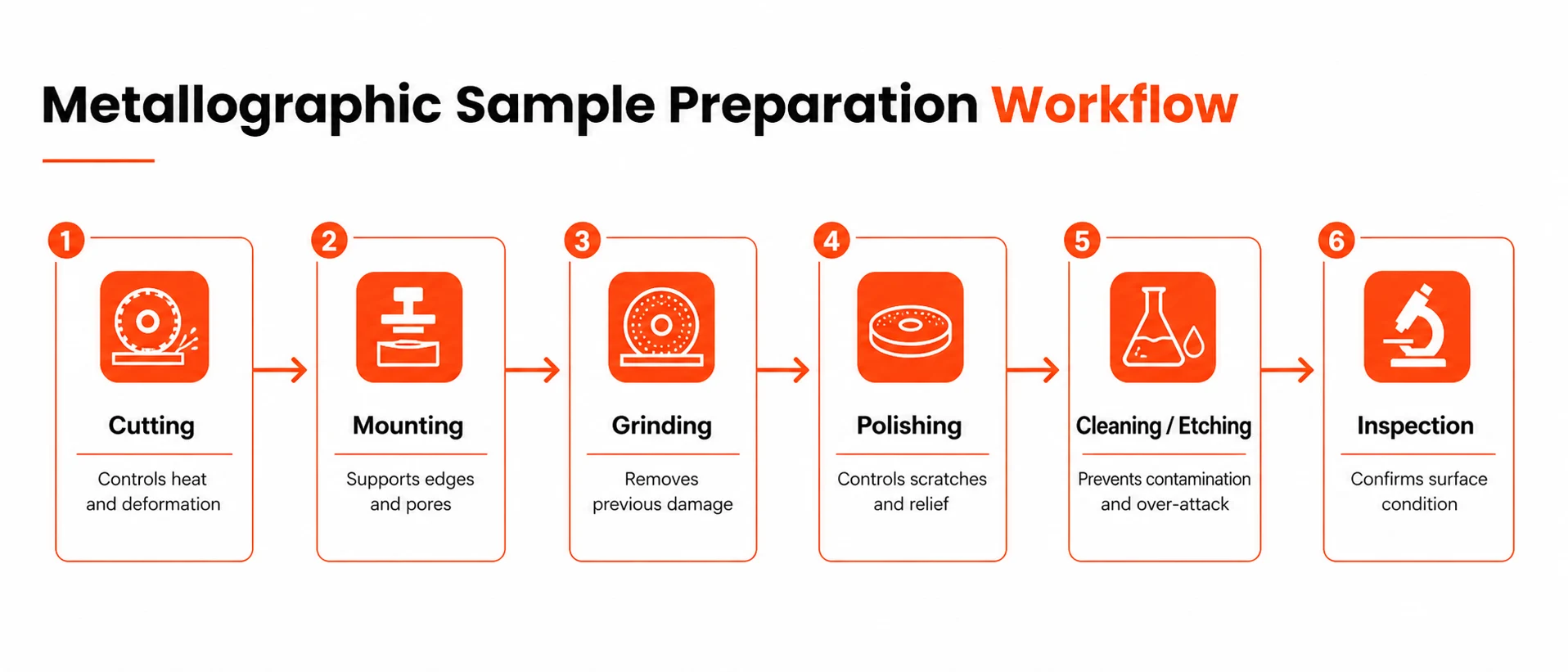
Most of these problems start before the microscope. Sectioning can introduce heat damage. Mounting can leave edges unsupported. Grinding can leave deformation that later polishing does not fully remove. Polishing can add contamination, relief, or embedded abrasive if the process is not controlled.
This guide reviews the most common metallographic preparation artifacts, how they usually form, where they affect interpretation, and what process adjustments help reduce them during cutting, mounting, grinding, polishing, cleaning, and etching.
What Are Metallographic Preparation Artifacts?
Metallographic preparation artifacts are marks, damage, or surface changes introduced during specimen preparation rather than by the original material condition.
Artifacts can be mechanical, thermal, chemical, or contamination-related. They may appear during sectioning, mounting, grinding, polishing, cleaning, or etching. The practical risk is misinterpretation. An artifact can resemble a real material feature or interfere with the feature being evaluated.
| Artifact source | Typical result |
| Mechanical force | Scratches, deformation, pull-out, relief |
| Heat during cutting | Burn marks, smearing, altered near-surface structure |
| Poor mounting support | Edge rounding, coating damage, particle loss |
| Contamination | Random scratches, embedded abrasive, staining |
| Etching errors | Low contrast, pitting, exaggerated grain boundaries |
A preparation artifact may look like a crack, pore, inclusion, coating defect, phase boundary, or corrosion pit. Artifact identification should come before microstructural interpretation.
Scratches from Grinding or Polishing
Scratches usually come from uncontrolled abrasive contact. The visible line is only part of the issue. Deformation can remain beneath the surface after the scratch pattern is reduced. If a coarse scratch pattern is not removed before the next step, finer polishing may only make the surface appear cleaner while the deeper damage remains.
Scratches often become more visible after etching because grooves can trap etchant, polishing residue, or contamination. They can cross grain boundaries, coatings, inclusions, or suspected cracks, which makes inspection less reliable.
Common causes include:
- moving to a finer abrasive too early;
- skipping abrasive steps;
- using contaminated polishing cloths or papers;
- leaving coarse particles on the specimen, holder, or platen;
- applying too much pressure;
- using the wrong abrasive for the material;
- polishing for time instead of checking whether the previous damage was removed.
A controlled grinding and polishing sequence should remove damage step by step. Each stage should eliminate the marks from the previous stage before the sample moves forward.
| Problem during preparation | What it can create |
| Coarse abrasive carried into fine polishing | Random deep scratches |
| Previous grinding marks not removed | Parallel scratches that remain after polishing |
| Dirty holder or platen | Repeated scratch patterns |
| Excessive pressure | Deeper deformation beneath visible scratches |
| Wrong polishing cloth or abrasive | Poor scratch removal, new surface damage |
To reduce scratching, clean the specimen, holder, platen, and working area between steps. Use dedicated cloths and consumables for each abrasive size. When preparing high-value or failure-analysis samples, inspect the surface between stages instead of waiting until final polishing.
Final polishing should not be used to correct deep grinding damage. If the earlier step leaves scratches or deformation behind, the process should return to the correct abrasive stage instead of extending the final polish.
Smearing and Deformation
Smearing occurs when ductile material is pushed or dragged across the specimen surface during cutting, grinding, or polishing. Instead of being removed cleanly, the metal deforms and spreads over nearby surface features.
Smearing is most often seen in softer metals and ductile alloys, including aluminum, copper, lead alloys, tin alloys, soft steels, some stainless steels, and ductile nickel or cobalt alloys. The smeared layer can cover small pores, inclusions, cracks, phase boundaries, and other features needed for inspection.
Smearing often starts with excessive mechanical force. High grinding pressure, aggressive polishing, poor lubrication, insufficient coolant, or the wrong abrasive can all increase plastic deformation at the surface. Cutting can also contribute if the wheel is dull, the feed rate is too high, or the sample overheats before grinding begins.
Reducing smearing requires less force and better control of material removal. Use appropriate abrasives, maintain effective coolant or lubrication, avoid overheating during sectioning, and select polishing conditions that remove deformation instead of spreading the material across the surface.
Pull-Out of Inclusions, Carbides, or Coatings
Pull-out occurs when particles, inclusions, carbides, coating fragments, graphite, brittle phases, or weakly supported material are removed from the specimen during preparation. The remaining voids can be misread as porosity, pitting, coating failure, or material damage.
This artifact appears often in cast materials, coated samples, powder metallurgy parts, composites, porous structures, and alloys with hard particles in a softer matrix. It is also common when the interface between a coating and substrate is weak or poorly supported before grinding.
The main causes are poor mounting support, aggressive grinding, large abrasive jumps, brittle constituents, weak interfaces, and excessive cleaning force. Porous or cracked specimens are especially sensitive because loose material can be removed during polishing or ultrasonic cleaning.
Prevention starts before grinding. Fragile, coated, porous, or irregular specimens should be mounted in a way that supports edges, fills voids where needed, and stabilizes interfaces. During grinding and polishing, use controlled force and avoid aggressive steps that can fracture or remove the features being examined.
Edge Rounding
Edge rounding develops when material is removed unevenly near the specimen boundary during grinding or polishing. It matters most when the inspection target sits at or near the surface.
This includes coating thickness checks, plating evaluation, case-depth measurement, carburized or nitrided layers, decarburization studies, weld edges, surface cracks, and fracture origins. In these cases, the edge is part of the measurement area. If it is rounded during preparation, the cross-section no longer represents the original surface geometry accurately.
The most common cause is weak edge support. A soft mounting material, poor edge retention, or a small gap between the specimen and the mount allows the edge to wear faster than the rest of the surface. Polishing conditions can make the issue worse. High pressure, long polishing times, and soft or high-nap cloths tend to remove more material near unsupported edges.
Edge rounding is easier to prevent than correct. The specimen should be mounted with firm support around the area of interest, especially when coatings, hardened layers, or surface defects are being examined. Polishing should be controlled for flatness, not speed. Lower pressure, shorter final polishing, and a cloth selected for edge retention can reduce material loss near the boundary.
When repeatability matters, controlled grinding and polishing equipment helps keep force, time, and speed consistent between specimens. Mounting materials and consumables should also be selected based on the inspection goal, not only on preparation convenience.
Relief Between Hard and Soft Phases
Relief forms when different phases or constituents in a material polish at different rates. Softer areas are removed faster, while harder particles, phases, or inclusions remain raised above the surrounding matrix.
This artifact is common in cast irons, carbide-containing steels, metal matrix composites, welds with mixed microstructures, coated samples, and alloys with hard inclusions in a softer base material. The prepared surface may look clean under low magnification, but at higher magnification the height difference between phases can affect contrast and measurement.
Relief affects work that depends on accurate phase shape, size, distribution, or area fraction. Raised hard phases may appear larger or more defined than their actual polished cross-section. Softer regions may look recessed. In image analysis, this can affect thresholding, boundary detection, and the apparent percentage of each phase.
The usual causes are excessive polishing time, high pressure, cloths with too much nap, or an abrasive that removes one phase more aggressively than another. Over-polishing is a common trigger. Once the previous preparation damage has been removed, additional polishing may increase relief instead of improving the surface.
Reducing relief requires a flatter, more controlled polishing approach. Pressure should be lowered, polishing time should be limited, and the cloth should be selected for phase flatness rather than fast material removal. Abrasive choice also matters because materials with large hardness differences often respond poorly to a generic polishing sequence.
For samples with mixed hard and soft phases, the preparation method should be checked under the microscope before final etching or image analysis. If relief is visible, extending the same polishing step usually makes it worse. The correction should target cloth type, pressure, abrasive selection, or step time.
Thermal Damage from Cutting
Thermal damage starts during sectioning when the cut generates more heat than the material, wheel, coolant, or feed rate can handle. By the time the specimen reaches grinding and polishing, the surface layer may already be changed.
This can show up as discoloration, burn marks, smeared material, local hardness variation, tempering effects in steels, or microcracking in brittle materials. In heat treatment evaluation, weld inspection, and failure analysis, the damaged area may overlap the region being examined.
The usual causes are wrong wheel selection, insufficient coolant, excessive feed force, poor clamping, vibration, or a cutting method that does not match the sample geometry or material. A small coated sample, a hardened steel part, and a soft aluminum component require different cutting conditions.
Prevention starts with controlled sectioning. The wheel or blade should match the material, coolant flow should reach the cutting zone, and the specimen should be clamped securely. Feed rate matters as much as wheel choice. If the cut is forced, heat and deformation increase.
For small, delicate, coated, or heat-sensitive samples, precision cutting is often the safer approach. It gives better control over feed, contact, and sample positioning, which helps reduce heat input before grinding begins.
A burned or altered cut surface should not be treated as a polishing problem. Grinding may remove visible marks, but it cannot reverse microstructural changes caused by excessive heat below the surface.
Staining, Corrosion, and Contamination
Staining, corrosion, and contamination usually come from cleaning control rather than from the polishing sequence itself. They can still affect inspection, especially when the sample is used for documentation, image analysis, or comparison between production batches.
Common sources include polishing residue, dirty coolant, contaminated cloths, abrasive carryover, drying marks, corrosion after etching, and particles trapped in pores or cracks. Even light handling can leave marks that become visible under the microscope.
Control comes from disciplined cleaning between steps. The specimen, holder, platen, and work area should be cleaned before moving to a finer abrasive. Polishing cloths and consumables should stay separated by abrasive size, and contaminated cloths should be replaced instead of reused.
After rinsing, the specimen should be dried quickly and handled only by the mount or edge. If corrosion appears after etching, the rinse and drying method should be checked first. Extending polishing time does not address contamination at the source and may introduce additional surface changes.
For porous, cracked, or coated samples, cleaning needs more care. Residue can stay inside voids or along interfaces, while aggressive cleaning can remove weakly supported features. The method should clean the surface without changing the area being inspected.
Over-Etching and Under-Etching During Metallographic Preparation
Etching should be controlled according to the alloy, surface condition, and feature of interest. The same specimen can produce different results depending on etchant selection, exposure time, surface cleanliness, and application method.
Under-etching leaves the structure with low contrast. Grain boundaries may be difficult to see, phases may not separate clearly, and fine features can remain hidden. Over-etching pushes the reaction too far. The surface becomes too strongly attacked, grain boundaries can appear wider or darker than they should, and fine detail may be lost.
| Etching issue | Typical result |
| Under-etching | Low contrast, weak grain boundary definition, unclear phase separation |
| Over-etching | Surface attack, pitting, exaggerated grain boundaries, loss of fine detail |
Etching problems often begin before the etchant is applied. A scratched, stained, contaminated, or poorly polished surface will not etch evenly. This can make the operator adjust the etching time when the actual issue is preparation quality.
To control etching, the specimen should be polished and cleaned properly first. The etchant should match the alloy and the inspection goal. Exposure time, application method, rinsing, and drying should be consistent between samples.
Detailed etchant selection and handling should follow lab procedures, safety data sheets, and recognized standards such as ASTM E407. Detailed chemical handling, concentrations, and exposure procedures should remain within approved lab methods and safety documentation.
How the Right Equipment Reduces Preparation Artifacts
Most preparation artifacts trace back to variables that can be controlled earlier in the workflow. Heat during cutting, weak edge support, abrasive carryover, inconsistent pressure, and poor polishing repeatability can all change the condition of the prepared surface.
The equipment setup should match the artifact pattern the lab is seeing. A lab dealing with heat damage needs better sectioning control. A lab seeing edge rounding or pull-out should look first at mounting support. If scratches, relief, or smearing keep appearing, the grinding and polishing sequence, force control, and consumables should be reviewed.
Controlled Cutting for Heat-Sensitive or Larger Samples
Cutting is often the first place where preparation damage begins. If the sample overheats or moves during sectioning, later grinding and polishing may not fully remove the affected layer.
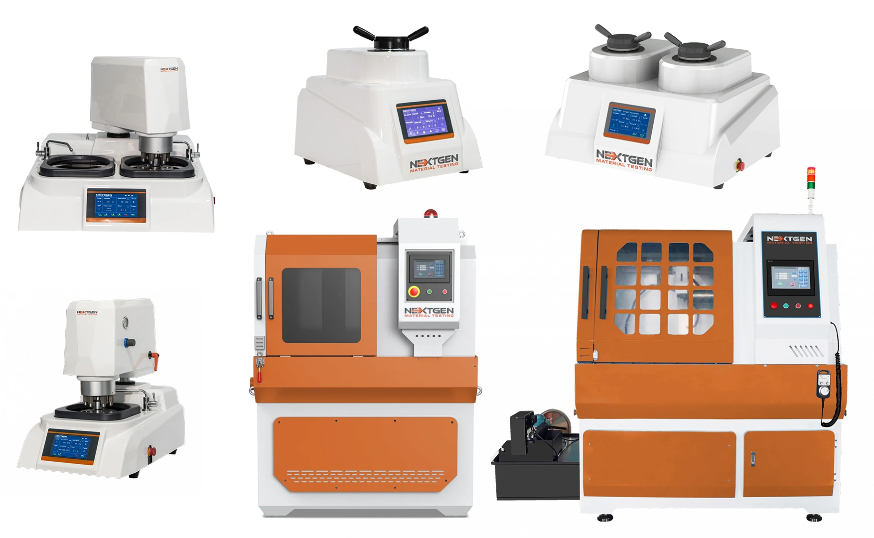
For routine sectioning and larger metallographic samples, an abrasive cut-off saw can help control cut geometry, coolant flow, and operator variation. The GenCut GL 170XY is designed for larger abrasive metallographic cutting, with a 170 mm maximum cutting capacity and a fully automated XY table. The GenCut abrasive cutting line also includes a recirculating coolant system to help reduce overheating during cutting.
This type of system is useful when the lab prepares:
- larger production samples;
- flat, tubular, or irregular specimens;
- samples that require straight or angular cuts;
- repeat cuts where positioning and coolant control matter.
Precision Cutting for Small, Delicate, or Coated Specimens
Small components, coated sections, delicate parts, and heat-sensitive materials often require more controlled sectioning than routine production samples.
For these applications, the GenCut GL100E provides low-speed automatic precision cutting with variable speed control from 50 to 1000 rpm and a maximum cutting diameter of 25 mm. NextGen’s precision cutting systems are designed for preparing specimens before hot or cold mounting for microscopy.
Precision cutting is especially relevant when the lab needs to protect:
- coating interfaces;
- thin sections;
- small failure-analysis samples;
- brittle materials;
- samples where heat or deformation near the cut would affect interpretation.
Mounting Support for Edges, Coatings, and Porous Samples
Mounting controls how well the specimen is supported during grinding and polishing. Poor support can lead to edge rounding, pull-out, coating damage, and loss of material around pores or weak interfaces.
The GenPress MFA HYD is a fully automatic hydraulic mounting press for compression mounting of metallographic samples. It is designed for 1 to 2 inch, or 25 to 50 mm, mold assemblies. NextGen’s mounting press systems are intended to help handle difficult specimen shapes and sizes while supporting sample edges and surface defects during preparation.
For porous or irregular materials, vacuum impregnation can be useful before grinding. The GenVac MP Series is designed for precision sample impregnation of porous materials, including ceramics, rocks, minerals, electronic circuit boards, and composite materials.
This stage matters most when preparing:
- coatings and plated parts;
- case-hardened or nitrided layers;
- porous samples;
- brittle materials;
- composites;
- samples with weak edges or interfaces.
Grinding and Polishing with Repeatable Force, Speed, and Time
Grinding and polishing are where many visible artifacts appear: scratches, smearing, relief, pull-out, and inconsistent finish. The issue often comes from variation in pressure, speed, abrasive sequence, cloth condition, or polishing time.
For labs that need more repeatability, automated grinding and polishing equipment can reduce operator-to-operator variation. The GenGrind FA-IC 250D is a 10 inch dual-wheel fully automatic grinder and polisher with variable speed from 100 to 1400 rpm, individual and central force control, touch screen control, and an automatic specimen mover power head.
Those controls are useful when the lab needs to keep preparation consistent across multiple samples, shifts, or operators. Individual and central force control can also help when different materials require different pressure strategies during grinding and polishing.
Consumables Still Decide the Final Result
Machine settings control force, speed, and time, while consumables control how the material is cut, ground, polished, and cleaned. Cutting wheels, abrasive papers, polishing cloths, diamond suspensions, mounting materials, and cleaning supplies should match the material and the inspection goal.
Incorrect consumables can create artifacts even when machine settings are consistent. A cloth that is too soft can increase edge rounding or relief. A contaminated polishing pad can add random scratches. A poor abrasive sequence can leave damage that final polishing cannot remove.
For artifact reduction, consumables should be selected around the failure pattern:
- scratches point to abrasive sequence, cleaning, or cloth contamination;
- smearing points to pressure, lubrication, abrasive type, and polishing method;
- pull-out points to mounting support and grinding aggressiveness;
- edge rounding points to mounting material, cloth type, and polishing time;
- thermal damage points back to cutting wheel, coolant, and feed control.
If the same artifacts appear across different samples, the workflow should be reviewed from sectioning through final polishing. Repeating defects usually point to a process variable, not a microscope issue.
Reducing Artifacts Starts with a Controlled Preparation Workflow
Metallographic artifacts often build across several preparation steps. A scratch may start with the abrasive sequence, but become worse because of poor cleaning. Edge rounding may begin with weak mounting support, then increase during final polishing. Thermal damage may appear during cutting, but only become obvious after etching.
The most effective way to reduce artifacts is to review the full preparation workflow:
- how the sample is cut;
- how edges, coatings, pores, or fragile areas are supported;
- how grinding and polishing pressure are controlled;
- how consumables are selected and separated;
- how the sample is cleaned, etched, and inspected between stages.
Controlling these steps helps the lab separate material features from preparation damage. This matters in routine quality control, coating inspection, weld evaluation, heat-treatment verification, and failure analysis.
If your lab is working to reduce metallographic preparation artifacts, NextGen Material Testing offers equipment for each stage of the workflow, including abrasive cutting, precision cutting, mounting, grinding and polishing, consumables, and microscopy.
Explore our metallography sample preparation equipment or contact our team to discuss your materials, sample sizes, preparation volume, and the artifacts you need to control.