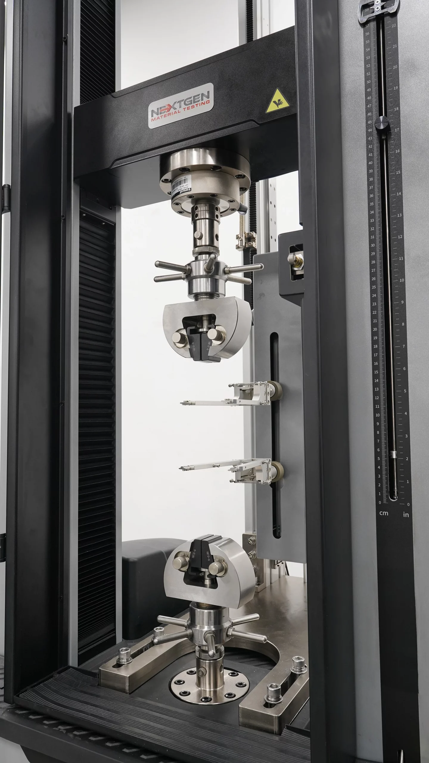
Your UTM may be calibrated, but if the specimen slips, bends, or fails at the jaws, you’re not measuring the material, you’re measuring the setup. A universal testing machine can only capture true material behavior when the load is transferred into the specimen the way the test method assumes. In practice, many repeatability and accuracy problems start right at the interface between the machine and the specimen: the grips or fixtures, the jaw faces, and the load-train alignment.
When that interface is wrong, specimens can slip, crush, neck prematurely at the jaw edge, crack from stress raisers, or pick up bending from misalignment. ASTM E8/E8M warns that the specimen axis should coincide with the machine head centerline to ensure axial stress in the gauge length, because misalignment can introduce bending stresses that are not included in the usual stress calculation.
In this blog, we’ll walk through the main UTM grip and fixture types, what each one is used for, and a practical, standards-minded way to choose the right setup based on your material, specimen geometry, and test method.
Grips Vs. Fixtures: What’s The Difference?
In test labs, the distinction is practical:
 Grips are designed to hold the specimen and transfer axial load into it, most often in tension, so the gauge section sees the intended stress state without slip or unintended bending. If the gripping method is wrong for the specimen, you’ll typically see interface-driven problems such as slippage, jaw break, crushed ends, or premature failure at the grip edge.
Fixtures are designed to create a defined loading arrangement by controlling contact points, spans, angles, or constraints. They’re what turns “a force from the crosshead” into a specific test mode like compression, 3-point/4-point bending, shear, peel, or puncture.
Why The Difference Matters (And How It Shows Up In Your Data)
If you use a “grip-like” setup for a test that is actually fixture-defined, you can create the wrong stress distribution and end up measuring something other than what the method intends.
Example: Flexural testing is fixture-defined.
A 3-point bend test requires a defined span and loading anvils. The uniform stress region is small and concentrated under the center loading point, which is why anvil geometry, span, and seating matter for repeatable results.
Similarly, peel or puncture tests require specific geometries to produce comparable results to the method’s definition.
Example: Floating-roller peel is geometry-defined.
It’s specified for a rigid + flexible adherend configuration under defined conditions and peel geometry.
Example: Index puncture is geometry-defined.
It uses a defined probe and support geometry and includes explicit limitations, including that products with large openings (for example, geonets/geogrids) may not be suitable for this method.
A Sharp “Problem Symptom” Explanation You Can Keep
Wrong grip: slip, jaw break, grip-edge failure, crushed specimen, or bending from jaw motion or asymmetry.
Wrong fixture: wrong stress distribution (for example, unintended shear in a bending test, or wrong peel geometry), so the reported property may not correspond to the standard’s definition.
The 3 Things Every Grip/Fixture Must Deliver
Even the best UTM can only produce trustworthy data if the load is introduced into the specimen the way the method assumes. That means the grip or fixture is not a “holder.” It is part of the measurement system. When labs see inconsistent curves, unexpected failures, or “mystery” scatter, the root cause is often at the interface: how the specimen is clamped, how the load train is aligned, and whether the geometry truly matches the standard setup.
A practical way to avoid that is to treat every grip or fixture choice like a mini acceptance checklist. Before you worry about brand, style, or convenience, the setup has to deliver three fundamentals.
1) Reliable Holding Without Damaging The Specimen
First, the grip must transfer load without slip, and it must do it without changing the specimen in a way that biases the result. In practice, the two classic failure modes are:
- Slip, where the crosshead displacement no longer represents specimen strain (your curve looks “soft,” noisy, or non-physical).
- Damage at the grip interface, where the specimen crushes, cuts, or cracks at the jaw edges, so the test fails outside the gauge length.
This is why jaw-face choice is never a detail. Smooth faces reduce surface damage but can slip on low-friction materials. Serrated faces increase friction but can introduce stress raisers, especially on thin sections or brittle materials. Rubber-coated or padded faces can help with films and soft materials, but they can also allow local compliance if they’re too soft for the load level.
For higher-load tensile testing, wedge-action grips are widely used because the clamping can increase as tensile load rises. That self-tightening behavior is useful when you need secure holding on metals, composites, and many rigid plastics, especially when the goal is to prevent slip without overtightening before the test begins.
2) Coaxiality, Minimal Bending, And Repeatability
Second, the setup must keep the specimen coaxial in the load train so the gauge section sees the intended axial stress state. Misalignment is not just “noise.” It can introduce bending stresses that are not included in the usual stress calculation (force divided by area). Tensile standards explicitly warn that the specimen axis should coincide with the machine’s loading axis to ensure axial tensile stress in the gauge length. If you introduce bending, you can systematically bias elastic modulus, yield behavior, and even apparent strength.
Repeatability also lives here. Two tests can use the same specimen and the same machine, yet produce different results if the alignment varies run to run. That is why alignment and centering features matter in real lab life: consistent seating, anti-rotation behavior, stable jaw motion, and fixtures that don’t “walk” or tilt under load. For standards-driven labs, alignment verification is its own discipline, and there are established methods specifically intended to quantify bending in the elastic range so you can confirm the load train is behaving as intended.
3) Adequate Capacity And Method Compliance
Third, the grip or fixture has to match the method’s boundary conditions, not just “fit on the machine.” That means:
- Capacity: the grip/fixture must safely handle the peak load with margin, including dynamic effects and any overload events.
- Specimen geometry compatibility: thickness/diameter range, width, shoulder shape, thread engagement, or wrap path, depending on the test.
- Environment: temperature range, chamber clearance, and whether the clamping method remains stable in hot/cold conditions.
- Standard geometry: spans, anvil radii, peel angles, roller paths, probe and ring dimensions, and other details that define the stress distribution.
If a grip or fixture satisfies these three requirements, the rest of the selection becomes straightforward: you choose the operating principle that best matches the specimen form and the workflow (manual vs pneumatic vs hydraulic), and you tune jaw faces, alignment strategy, and geometry to the specific standard you’re running.

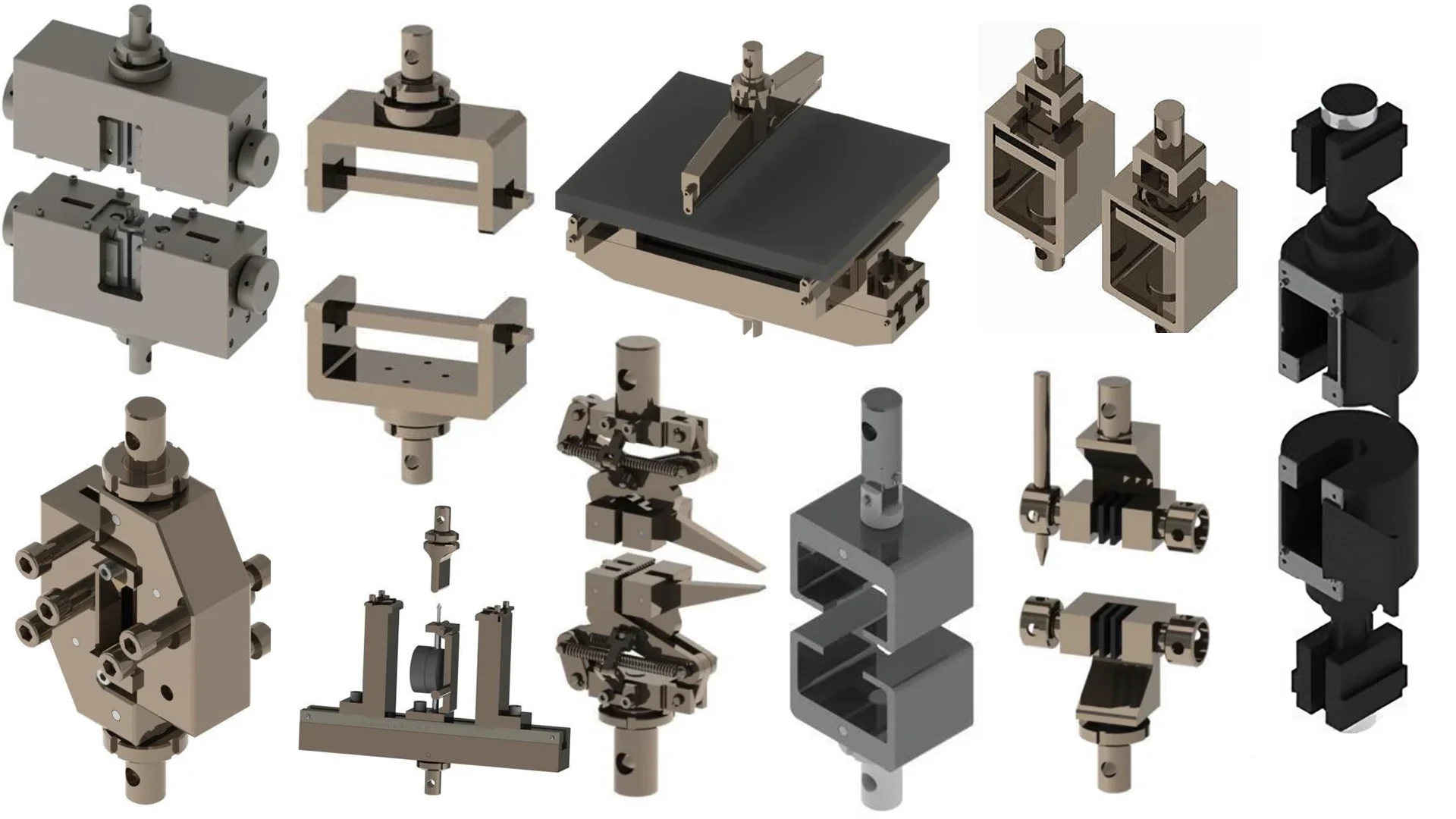
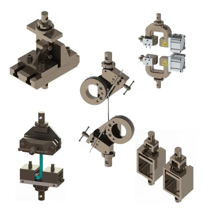
Types Of UTM Grips And Where They’re Used
In tensile testing, the “right” grip is the one that transfers load into the specimen the way the test method assumes, without slip, crushing, or unintended bending. In practice, grip selection comes down to three variables: how load is transferred (friction vs. positive engagement), how sensitive the specimen is to contact pressure and stress concentrations, and how repeatable and fast the workflow needs to be.
Wedge Grips (Self-Tightening For Higher Loads)
Wedge grips are widely used for metals and other high-strength specimens because wedge geometry naturally increases clamping force as tensile load rises. This self-tightening behavior helps reduce slippage at higher forces, especially in standardized tensile programs such as those commonly associated with ASTM E8/E8M and ISO 6892.
Selection details matter. The clamping performance depends heavily on jaw-face configuration and how it matches specimen shape and surface condition. Flat jaw faces are typically used for flat coupons and sheet specimens, while V-shaped faces are used for round specimens. Serration pitch and jaw hardness influence both holding power and the risk of introducing stress raisers or grip-edge failures, which is why jaw selection is often the first place engineers look when breaks occur near the grips or results show unexplained scatter.
Side-Action Mechanical Grips (Simple And Versatile)
Side-action mechanical grips are screw-driven or mechanically actuated clamps commonly used when flexibility and frequent specimen changes are priorities. They are a practical choice across plastics, textiles, rubber, and films, particularly in labs that run many specimen geometries and prefer a simple, durable solution without needing compressed air.
Interchangeable jaw faces are a key advantage. Smooth faces can reduce surface damage but may slip on low-friction materials; serrated faces improve holding but can increase stress concentration; rubber-coated faces can help with delicate or thin specimens but may add compliance depending on load level. Side-action grips are often the rational choice when throughput is moderate, air supply is limited, and operators need fine control and quick jaw swaps.
Pneumatic Grips (Fast, Repeatable Clamping)
Pneumatic grips are commonly selected for quality control and high-throughput environments where repeatability and speed matter. The main benefit is consistent gripping force across tests, which reduces operator-to-operator variation and helps stabilize results across shifts. They also shorten the load and unload cycle, which becomes significant when testing many samples per day.
Pneumatic actuation can be paired with different grip styles, including side-action and wedge-action designs, depending on specimen type and the required force range. In practice, pneumatics are most justified when the lab is chasing both speed and repeatability, not just convenience.
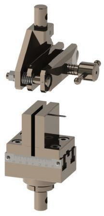
Self-Tightening Grips (For Elastomers, Foams, Fabrics)
Self-tightening grips are designed for specimens that thin or neck significantly during loading, or for materials with low-friction surfaces where a fixed pre-tightened clamp can either slip later in the test or crush the specimen early. In these materials, large deformation changes the contact conditions at the jaws, so the grip needs to maintain holding power as the specimen geometry evolves.
Typical applications include elastomers, soft polymers, foams, fabrics, and thin flexible laminates. Common mechanisms include cam-action and scissor-style designs that increase gripping force as tensile load increases, helping maintain stable load transfer through high elongation.
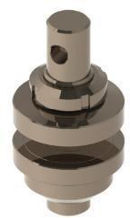
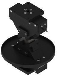
Eccentric Roller Grips (For Thin, Flexible Specimens)
Eccentric roller grips are a specialized self-tightening option for thin, flexible, high-elongation specimens such as rubber and plastic film. They are often used when conventional jaw faces force a trade-off between slipping and tearing: serrations may prevent slip but initiate edge tears, while smooth faces avoid damage but slip as the specimen stretches and its cross-section reduces.
Roller-based designs can reduce stress concentration at the grip edge and “follow” the specimen as it elongates. An eccentric cam mechanism increases grip force with tensile load, helping prevent slippage while minimizing surface damage.
Snubbing/Capstan Grips (For Wire, Rope, Cable)
Snubbing or capstan grips use a wrap path around a mandrel or capstan to generate friction and distribute load over a longer contact length. This is especially useful for wire, rope, fiber bundles, and cable products where direct clamping can cause localized damage, premature breaks at the clamp, or inconsistent results.
By spreading contact pressure and relying on controlled friction, capstan designs reduce peak stresses and improve the stability of load transfer. They are typically chosen when preserving the specimen surface matters and when the product geometry makes conventional jaw clamping unreliable.
Threaded Grips And Fastener Testing Fixtures (Bolts/Nuts)
Threaded grips load fasteners through threaded engagement, creating a direct and repeatable load path for tensile and proof-type verification of bolts and nuts. They are commonly used in programs aligned with standards such as ASTM F606 and ISO 898.
Alignment is especially important in fastener testing. If the load path is eccentric, bending stresses can be introduced that were not intended by the method, which can bias results or cause premature failures. Practical selection factors include thread size range, engagement requirements, adapter/bushing needs for alignment, and the expected force range.
Shoulder Fixtures / Component Pull-Off
Shoulder-style fixtures are used when specimens have shoulder geometries or when component or bonded assembly tests require repeatable seating and centering. These setups are often chosen to reduce parasitic bending and to load the specimen through defined end features that help keep the load path coaxial.
They are common in component pull-off style testing and in applications where fixture geometry defines the boundary conditions that make results comparable and repeatable.
Fixtures Commonly Paired With Grips
Grips mainly solve the “holding” problem. Fixtures solve a different problem: they create the loading geometry that a test method assumes. In other words, fixtures control the boundary conditions that determine the stress state in the specimen. This is why two labs can use the same UTM and still get different results if their spans, anvils, radii, peel angles, or contact geometries are not equivalent.
Below are the fixture families most commonly paired with grips, grouped by loading mode and the kind of results they are used to generate.
Compression Platens And Compression Fixtures
 Compression testing often looks straightforward, but it is highly sensitive to eccentric loading, specimen seating, and end conditions. Small seating errors can introduce bending or non-uniform contact pressure, which can change apparent compressive strength, modulus, or failure mode.
A basic compression setup typically uses two platens (upper and lower). The key decision is whether you need features that help the specimen “find” a coaxial load path:
- Sphere-seated (self-aligning) platens are used when improved alignment is needed. They help compensate for minor lack of parallelism or uneven seating so the specimen is loaded more uniformly.
- Guided compression fixtures or additional supports may be used for slender specimens that are prone to buckling, or when the method requires constrained end conditions.
Common standards in this category include plastics compression methods (such as ASTM D695 and ISO 604) and metals compression methods (such as ASTM E9). The important selection logic is always the same: match the fixture geometry and seating behavior to the method’s assumptions and your specimen’s stability risk.
3-Point Vs. 4-Point Bending Fixtures
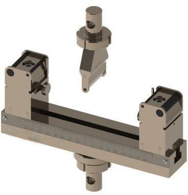 Bending tests are fixture-defined by design. The fixture sets the support span and how the load is introduced. The choice between 3-point and 4-point bending is not just preference; it changes the stress distribution and, therefore, how and where failure initiates.
3-point bending
- The specimen is supported on two lower anvils with a single loading nose at midspan.
- The maximum bending moment occurs at the center, directly under the loading nose.
- The region of “uniform” stress is small and concentrated around midspan, which is why contact geometry (nose radius, support radius, and seating) strongly influences results and failure location.
4-point bending
- The specimen is supported on two lower anvils and loaded by two upper noses.
- The area between the two loading noses experiences a more uniform bending condition (often described as a “constant moment” region), which can be useful when you want failure to reflect material behavior over a larger section rather than at one highly concentrated point.
How to choose in practice:
- Use 3-point bending for simpler setups and when the standard specifies it, especially for routine comparisons.
- Use 4-point bending when the goal is a more uniform bending distribution, when localized stress under a single nose may dominate failure, or when the method calls for it.
Standards commonly associated with bending fixtures include plastics flexural tests (ASTM D790, ISO 178), composite flexural tests (ISO 14125), and ductility bend testing for metals (ASTM E290). Concrete flexural testing is also commonly standardized with defined bending geometries (for example, ASTM C78).
Shear And Composite Fixtures
 Shear and composite testing is a classic example of why fixtures exist. A tensile grip can apply force, but it cannot automatically create a clean shear stress state in the gauge section. In composites especially, “shear strength” depends heavily on how the specimen is constrained, notched, and loaded.
Two widely used approaches illustrate this:
- V-notched beam shear methods (commonly associated with Iosipescu-style concepts) use a notched specimen and a dedicated fixture to produce shear in a defined region. This is used to generate shear property data for R&D, quality assurance, and structural design.
- Rail shear methods clamp a V-notched specimen between loading rails. These setups are designed to produce a shear stress–strain response and ultimate shear strength under controlled boundary conditions.
Standards you’ll often see referenced in this space include ASTM D5379/D5379M (V-notched beam shear) and ASTM D7078/D7078M (rail shear).
For delamination and fracture-related work, fixtures become even more geometry-driven. Mode I interlaminar fracture toughness testing, for example, commonly uses a double cantilever beam (DCB) specimen and loading blocks that define how force is introduced. ASTM D5528 is a typical reference standard here. The key takeaway is that these fixtures are not “accessories.” They define the loading mode that makes the data meaningful and comparable.
Tear, Peel, And Puncture Fixtures
 Tear, peel, and puncture tests are not “just tensile” because the result depends on controlled geometry: peel angle, roller path, probe diameter, ring support size, and how the specimen is constrained. If the geometry is wrong, the measured value may no longer represent the property the method is trying to define.
Peel
- Peel tests control the angle and path of separation, which is why they require dedicated rigs.
- ASTM D903 is commonly used for comparative peel/stripping characteristics under defined conditions.
- ASTM D1876 is a comparative “T-peel” style test for adhesive bonds between flexible adherends, named for the specimen shape during loading.
- ASTM D3167 defines floating-roller peel for a rigid plus flexible adherend configuration and is often described as a more severe peel geometry due to the angle involved.
A practical setup issue in peel testing is alignment of the load string. When peeling a thin adherend from a thicker substrate, grip positioning can offset the load path, so fixture design needs to manage the geometry so results remain comparable.
Puncture
- Puncture methods define probe and support geometry explicitly because they are index-style tests meant for consistent comparison.
- ASTM D4833 is a common index puncture method for geotextiles, geomembranes, and related products and includes explicit limitations on what products it applies to.
Across tear/peel/puncture, the selection logic is consistent: choose fixtures that reproduce the method’s defined geometry (angles, rollers, rings/probes) and that match the specimen type (films, membranes, adhesive laminates, textiles) so the measured property corresponds to the intended standard definition.
How To Choose The Right Grip/Fixture
The most reliable way to choose grips and fixtures is to start from the test method and work outward to the hardware. Standards define the boundary conditions that make results comparable, so the goal is to select hardware that reproduces those conditions while keeping the specimen aligned and undamaged.
1) Test Type And Standard/Method
Begin by naming the test mode and method, because this immediately determines what geometry must be controlled.
- Tension usually needs a grip that can transfer axial load without slip or grip-edge failures.
- Compression typically needs platens and often self-alignment to avoid eccentric loading.
- Bending requires defined span(s) and loading nose geometry (3-point vs 4-point).
- Shear, peel, puncture are fixture-defined by geometry, not just “apply force.”
If you are testing to a standard tensile method, alignment is not optional. Tensile standards explicitly warn that the specimen axis should coincide with the machine loading axis to ensure axial stress in the gauge length; otherwise bending stresses can be introduced that are not included in the usual stress calculation.
2) Specimen Geometry And Form
Next, define what you are physically gripping or supporting. This is often the deciding factor.
- Flat coupons / sheet specimens: usually flat jaw faces and careful jaw-face selection to prevent slip without cutting the specimen.
- Round specimens (rods, pins): V-type jaw faces or other geometry that centers the specimen.
- Wire, rope, cable, fiber bundles: capstan/snubbing-style grips are often preferred because they spread load through a wrap path instead of crushing at a jaw line.
- Threaded fasteners: threaded fixtures/grips create direct load transfer through thread engagement, but they must be set up carefully to minimize eccentricity.
- Shouldered specimens or component pull tests: shoulder-style fixtures are typically used to seat the specimen consistently and help keep the load path coaxial.
A simple rule: the more the specimen is “non-standard” (thin films, braided rope, threaded parts, bonded assemblies), the more likely you need a specialized grip or a dedicated fixture.
3) Material Behavior
Material response under load determines whether you should prioritize friction, surface protection, or self-tightening mechanics.
- Brittle materials tend to be sensitive to stress concentrators. Aggressive serrations may initiate cracks at the grip edge.
- Ductile metals often benefit from high holding power and stable alignment, especially at higher loads.
- Elastomers, foams, fabrics, thin films can thin dramatically during a test. In these cases, fixed clamping can either slip later or crush early, which is why self-tightening and roller-style grips are commonly used.
- Low-friction surfaces (some films, coated materials) may need higher-friction jaw faces or grip types that increase clamping under load without damaging the surface.
If the specimen routinely fails at the jaws instead of the gauge section, that is usually a grip-interface problem (jaw-face choice, contact pressure, alignment), not a material problem.
4) Force Range And Safety Margin
Choose the grip/fixture capacity based on the peak force you expect, plus a realistic margin.
- Grips and fixtures should be rated to exceed the maximum expected load, not just “about equal.”
- Higher loads often push you toward wedge-action or hydraulic gripping approaches, while low-force testing can require more delicate gripping to avoid crushing or compliance effects.
Capacity is also tied to specimen size range. Jaw travel, thickness range, and jaw-face geometry must match your specimen dimensions.
5) Throughput And Repeatability Requirements
How many specimens you run matters almost as much as what you run.
- Manual/mechanical grips are typically best when throughput is moderate, setup flexibility is important, and the lab frequently changes specimen types.
- Pneumatic grips are often chosen when you need faster cycling and more consistent gripping force across operators and shifts.
- Hydraulic grips are commonly used for very high forces and industrial workflows, where uniform gripping pressure and automated clamping cycles are priorities.
If your primary problem is operator-to-operator variation, moving from manual clamping to controlled-actuation gripping is often the biggest repeatability upgrade.
6) Environment And Special Constraints
Finally, account for conditions that can change clamping behavior or fixture geometry:
- Temperature chambers (hot/cold): jaw materials, lubrication, and grip actuation can behave differently across temperature extremes.
- Corrosive or wet environments: surface condition and friction change, affecting slip risk.
- Space constraints inside chambers: fixture dimensions and clearances matter as much as ratings.
- Special requirements like anti-rotation, centering aids, or alignment verification (especially for standards-heavy or fatigue-sensitive labs).
A practical close-out step for standards-driven work is verifying alignment and minimizing bending in the elastic range, since alignment errors can quietly bias results even when everything “looks fine.”
Better Gripping And Fixturing Leads To Better Data
A universal testing machine can only deliver meaningful material properties when the specimen is held correctly and loaded in the geometry the method assumes. When grips and fixtures match the standard’s boundary conditions, you reduce common error sources such as slippage, grip-edge failures, unintended bending from misalignment, and geometry-driven bias in bending, shear, peel, or puncture setups. The payoff is simpler troubleshooting, tighter repeatability, and results that are easier to defend in audits, reports, and design decisions.
NextGen Inventory And Support: Find The Right Grip Or Fixture For Your UTM
 NextGen Material Testing maintains a broad inventory of UTM grips and fixtures for tensile, compression, bending, shear, peel, puncture, and specialty applications. Many options are compatible with our NG-EML series and with other universal testing machines, allowing labs to match the right hardware to specimen geometry, force range, and the requirements of ASTM/ISO test methods.
If you’re not sure which setup is best, we can help you narrow it down quickly. Request a quote or contact us with your material type, specimen dimensions, target standard, and expected force range, and we’ll recommend a suitable configuration and confirm compatibility.