If you’re looking for equipment that allows you to focus on precise, abrasive cutting of materials (including both soft and hard metals) look no further than our GenCut series. Housed within our precision metallography equipment category, this product grouping allows our clients to shape specimens into the exact size required for further analysis.
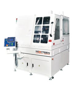
To learn more about the models of low-speed precision saws provided by industry leader NextGen, read summaries of each below.
GenCut GL 100 Series:
This series precision cutter includes our low speed diamond saw machines, which allow easy sectioning of delicate parts or materials with no deformation. This machine uses a thin diamond blade with continual lubrication and will not allow any burning to occur. This model allows for wheels with a 3″-5″ diameter and provides speed wheel control from 0-400 RPM.
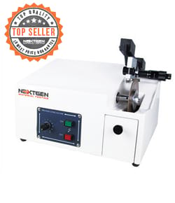
GenCut GL 200 Series:
Similar to the GenCut GL 100 Series, this machine uses a precision low speed diamond saw and again, allows you to cut and section wide variety of small and delicate samples. This model is notable for its ability to handle non-homogenous material structures.
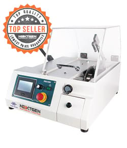
GenCut GL 600-800 Series:
This series low speed precision saw, which includes the 600, 700 and 800 models, is both compact and powerful. Conveniently designed as a table-top manual abrasive cutter, these models fit into any metallographic or materials oriented lab, making this machine particularly versatile. All three models of low speed diamond saws also provide a robust 1-3HP motor and are designed for heavy-duty continual use.
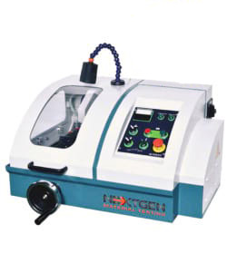
GenCut GL 1000 Series:
Like the GenCut GL 600-800 Series, the GenCut GL 1000 abrasive metallographic cut off machine series uses a laboratory design and will section any material with no deformation. This model also takes performance up a notch from the 100 and 200 series by using a high-speed (rather than low-speed) precision cutter and it also uses both diamond and abrasive blades. An added feature is that this model allows users to cut on X & Z axis to a perfect cut during every use.
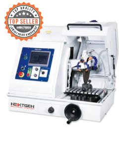
GenCut GL 2000 Series:
Performance meets advanced technology with this metallographic cutter model. An automatic cutter is complemented with a touch screen panel and provides simple positioning of samples for cutting and sectioning. It also goes one step further than the GenCut GL 1000 Series by allowing cuts in 2 directions, providing a large cutting capacity and programmable functions. This model also uses either an abrasive cut off blade or a diamond blade on variable rotational speed.
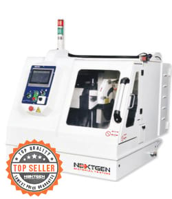
GenCut GL QA Series:
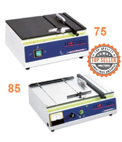
This model provides user control through the use of manual units. We recommend this model for specific section cutting from printed circuit boards, large flat materials or electronic components. Like the excited for section cutting from printed circuit boards, flat materials or electronic components. Like the GenCut GL 100 Series and the GenCut GL 200 Series, this model uses a diamond blade.
Whatever model of cutter you choose, you can be sure that our experts at NextGen Material Testing will be happy to help. Request quote today to get started with your specific metallography cut-off saw!
Keep Reading in Abrasive Metallographic Cutting
See the Abrasive Metallographic Cutting range Flexural (Bend) Testing Explained: 3-Point vs 4-Point, Standards, and SetupFlexural (bend) testing explained: what it measures, three-point vs four-point setups, the standards for plastics, metals, composites and concrete, and how to choose the right fixtures and...Read the articleGenTest Software Setup Guide for NextGen NG-EML Universal Testing MachinesGenTest setup affects the full UTM testing workflow: method storage, PC-to-controller communication, user permissions, simulation files, live data acquisition, and report output. This guide follows the GenTest setup video step by step for NextGen NG-EML electromechanical universal testing machines. It covers installation, license activation, workspace configuration, UTM controller connection, safety and peripheral setup, user management, DEMO Mode, simulation files, Control Panel setup, Quick Test, and test method creation. GenTest is the software layer where the test method, machine connection, operator input, live data, calculated results, and report output come together. For operators, service teams, QA/QC labs, and R&D users, the goal is to...Read the articleMetallography Sample Preparation Equipment: How to Improve Accuracy from Cutting to Final AnalysisAccurate metallographic analysis starts before the specimen reaches the microscope. Cutting, mounting, grinding, and polishing all influence whether the final surface reflects the material’s true structure or carries preparation-related damage. Excess heat, weak edge support, inconsistent pressure, poor abrasive progression, and unstable polishing conditions can all introduce artifacts that affect interpretation. Well-matched metallography sample preparation equipment helps control these risks across the full workflow. By improving sectioning control, mounting stability, and grinding and polishing repeatability, labs can produce more consistent specimens and reduce the chance that preparation defects are mistaken for real material features. Why...Read the articleBrinell, Rockwell, Vickers, or Microhardness: Which Test Makes Sense for Your Application?Choosing a hardness test starts with the part itself. Material type, section thickness, geometry, surface condition, inspection purpose, and required testing speed all affect which method will produce a reliable result. Brinell, Rockwell, Vickers, and microhardness methods work differently, so they are not equally suitable for the same component or the same quality task. Brinell, Vickers, and Knoop are based on the size of an indentation, while Rockwell is based on indentation depth. That difference directly affects how the result is obtained and where the method fits best. In production and lab work, problems usually appear when the test method does not fit the application. A part may be too thin for the selected load, the surface may be too rough...Read the article
Machines Behind This Article
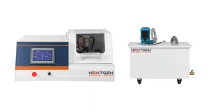 Precision Metallographic CuttingGenCut GL200E – High-Speed Precision Metallographic CutterGenCut GL200E is a high-speed automatic precision metallographic cutter for accurate sectioning of metals, ceramics, biological specimens, and other materials up to...View product
 Precision Metallographic CuttingGenCut GL100E – Low-Speed Precision Metallographic CutterGenCut GL100E is a low-speed automatic precision cutter for metallographic preparation of small and delicate specimens. Designed for metals, composites, ceramics,...View product
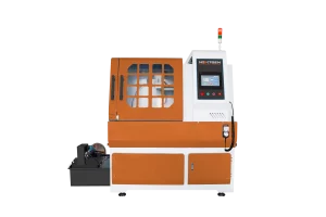 Abrasive Metallographic CuttingGenCut GL170XY – Multi-Function Abrasive Cut-Off SawGenCut GL 170XY is a large-capacity abrasive cut-off saw for automated metallographic sample cutting up to Φ170 mm. Its XY-axis movement, variable feed speed, large...View product
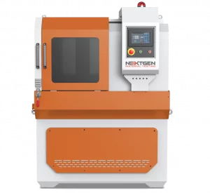 Abrasive Metallographic CuttingGenCut GL120XY – Multi-Function Abrasive Cut-Off SawGenCut GL 120XY is a multifunction abrasive cut-off saw for automated metallographic sectioning of metal specimens up to Φ120 mm. It features a fully automated XY...View product
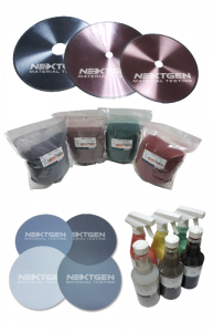 Abrasive Metallographic CuttingMetallography ConsumablesMetallography consumables cover the materials needed for sectioning, mounting, grinding, polishing, etching, and cleaning specimens before microscopic examination....View product