Hardness is the number a drawing falls back on when it has to say, in one figure, whether a part was heat treated correctly. The Vickers test is the method that produces that figure across the widest range of materials and the smallest features, from a case-hardened gear tooth to a thin coating to a weld and the heat affected zone beside it. It is also the method where the number depends least on the machine and most on how carefully somebody measured two diagonals.
This is how the test actually works: the geometry behind the HV number, the three ranges of force it runs at, the standards that govern it, and the places where the accuracy is genuinely won or lost.
The One Indenter and the Number It Produces
Every Vickers test on every material uses the same tool: a diamond in the shape of a right pyramid with a square base, with an angle of 136 degrees between opposite faces. That single geometry is the reason the method behaves the way it does. Because the indentation is always the same shape, indentations made at different forces stay geometrically similar, so one continuous scale covers soft aluminium and hardened tool steel without a change of indenter or a correction factor.
The hardness value is the test force divided by the sloping surface area of the indentation the diamond leaves. The operator measures the two diagonals of the square impression, averages them, and the machine turns that average into a number.
That last point is worth holding on to, because it explains the whole error story further down. Hardness goes as the inverse square of the diagonal. A small mistake in reading the diagonal becomes a larger mistake in the reported hardness, and the smaller the indentation, the more that leverage hurts.
How a Vickers Test Runs
The sequence is short, and each step exists because skipping it changes the number.
Surface preparation is the step most often underestimated. In practice it means the same progression used for metallographic samples, which is covered by ASTM E3 and described in our guide to metallographic sample preparation. On a production part that is a real operation with a real cycle time, not a wipe with a cloth.
Three Ranges of Test Force, One Scale
Vickers is often described as two methods, micro and macro, but it is one method run at different forces. ISO 6507-1 divides it into three ranges rather than two, and the boundaries are set in newtons rather than in the kilogram force units the scale is usually quoted in.
The force decides how much material the indentation averages over, and that is a metallurgical choice before it is an equipment choice. At the bottom of the range the indentation lands inside a single grain or a single phase and reports that feature. At the top it spans a coarse structure and reports the bulk. Neither is more correct; they answer different questions, and specifying the wrong one is how a casting gets rejected on the hardness of one carbide.
Because the same scale runs across all three ranges, a value only means something with its force attached. HV0.1 and HV30 taken on the same sample can legitimately differ, and on a fine or layered structure they usually do. Our overview of macrohardness against microhardness testing goes into where that split lands in practice.
Where the Accuracy Is Won or Lost
The Vickers machine applies a force and holds it. That part is straightforward, well controlled on any competent instrument, and rarely the problem. The measurement of the diagonals is where the number is decided, and the published metrology work is unusually blunt about it.
The UK National Physical Laboratory surveyed fifteen commercial hardness machines against its own national standard machines, on the HV10 and HV30 scales at nominal block hardnesses of 150, 300 and 800 HV. Repeatability was excellent. Even so, over half the values fell outside the two percent tolerance, and correcting the results for systematic errors and for the magnification of the microscope used to measure the diagonal brought the uncertainty back inside it. No single mechanical cause was found. Over half of the commercial measuring systems in that survey exceeded the permitted half percent magnification tolerance.
Read that chart next to the inverse square relationship and the conclusion is uncomfortable but useful. On a large macro indentation a two micrometre disagreement between two people is a rounding error. On a small micro indentation it is a double digit percentage of the hardness value, and no amount of machine calibration recovers it, because the machine did its job correctly and the disagreement happened afterwards, at the eyepiece.
This is the single strongest argument for taking the reading off a camera and software rather than a human eye, and for keeping certified reference blocks in the routine. It is also why the optics are the expensive part of a Vickers tester rather than an accessory to it.
The Limits the Standard Sets on the Method
ISO 6507-1 does not simply describe the test, it fences it. The test method is specified for indentation diagonals between 0.020 mm and 1.400 mm, and determining Vickers hardness from indentations smaller than that lower limit is stated to be outside the scope of the document. That is not a formality. It is the same physics as the chart above, written into the standard: below a certain size the diagonal cannot be measured well enough for the result to mean anything.
The practical consequence is that the lower end of the force range is bounded from two directions at once. The standard permits forces down to 0.009807 N, but it also requires that the force chosen produces a diagonal longer than 0.020 mm. On a hard material a very small force produces a very small indentation, and the two requirements collide. The force is therefore selected from the material and the feature together, not from the feature alone.
Choosing the Instrument
Once the force range is decided by the metallurgy, the instrument follows from two questions: how small the feature is, and how many indentations a shift has to produce. A single spot check and a two hundred point case depth map are the same test method and very different machines.
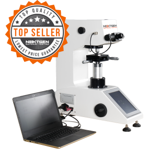
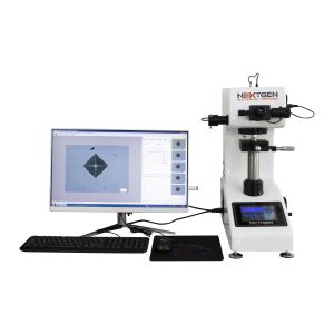
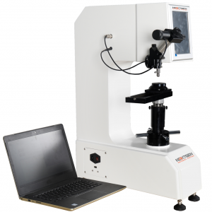
Automation changes the economics more than it changes the physics. A motorized turret removes the manual swap between indenter and objective after every indentation. A motorized stage plus analysis software lets an operator lay out a pattern of indentations, start it, and come back to a plotted result, which is what turns a case depth survey from an afternoon into a background task. The whole Vickers and Knoop range shares the same measurement principle underneath.
What Has to Be Right Besides the Machine
A Vickers result is only defensible if three things around the machine are in order, and all three are consumable or perishable in some sense.
The diamond comes first. It is the one part of the system in contact with every test, and its geometry sits inside the hardness equation rather than beside it: across the angle band the standard permits, measured hardness on the same block shifted by around four HV. A chipped or worn indenter does not announce itself in the reading, which is why indenter condition is checked rather than assumed.
Certified reference blocks come next. They are how a laboratory demonstrates on any given morning that the whole chain, force, diamond, optics and operator, still produces the right answer. NIST supplies microindentation hardness reference materials for exactly this purpose on the Vickers and Knoop scales, and NIST certified indenters and test blocks are available with our systems on request.
The optics and the software come third, and by the evidence above they carry most of the risk. A camera and analysis software do not make the method more accurate in principle. They remove the operator to operator spread that the metrology studies keep measuring, and they make the reading reproducible by somebody else six months later, which is usually what an audit is asking about.
Vickers Against Brinell, Rockwell and Knoop
Vickers earns its place through range and locality rather than speed. One indenter and one continuous scale cover materials that would need several Rockwell scales, and the indentation can be placed precisely enough to interrogate a single feature. Against that, the cycle is slower than Rockwell, which reads depth directly and gives a number in seconds without any optical step, and the surface preparation is far more demanding.
Against Brinell, Vickers works on much harder material and much smaller features, while Brinell’s large ball averages over coarse and inhomogeneous structures like castings in a way a small diamond cannot. Knoop, which shares the same machines and the same optical workflow, uses an elongated rhombic indenter whose long diagonal makes it better suited to very thin layers and brittle materials. If the choice is still open, our comparison of Brinell, Rockwell, Vickers and microhardness works through the decision by application.
Reading a Vickers Result on a Drawing
A hardness callout that says only a number and the letters HV is incomplete, and the ambiguity it leaves is not academic. The designation carries the force, and where the dwell differs from the normal range it carries that too, so a specification written as HV 10 and one written as HV 0.3 are asking the laboratory for two different tests on two different scales of feature.
Two habits cause most of the trouble in practice. The first is treating an HV number as convertible into another scale as though the conversion were exact. Conversions between hardness scales are empirical, they depend on the material, and a converted value is an estimate rather than a measurement; where a specification is written in one scale, the honest answer is to test in that scale. The second is quoting a hardness without the standard it was produced under, which, given that ISO and ASTM place their range boundaries in different places, can leave two laboratories running genuinely different tests against the same line on a drawing.
The fix is unglamorous and takes one line. State the scale with its force, name the standard and its part, and say where on the part the measurement is to be taken. A drawing that does that gets comparable numbers from any competent laboratory, and one that does not will eventually get two numbers that disagree for reasons nobody can reconstruct.
Keep Reading in Vickers and Knoop Hardness Testers
See the Vickers and Knoop Hardness Testers range Flexural (Bend) Testing Explained: 3-Point vs 4-Point, Standards, and SetupFlexural (bend) testing explained: what it measures, three-point vs four-point setups, the standards for plastics, metals, composites and concrete, and how to choose the right fixtures and...Read the articleGenTest Software Setup Guide for NextGen NG-EML Universal Testing MachinesGenTest setup affects the full UTM testing workflow: method storage, PC-to-controller communication, user permissions, simulation files, live data acquisition, and report output. This guide follows the GenTest setup video step by step for NextGen NG-EML electromechanical universal testing machines. It covers installation, license activation, workspace configuration, UTM controller connection, safety and peripheral setup, user management, DEMO Mode, simulation files, Control Panel setup, Quick Test, and test method creation. GenTest is the software layer where the test method, machine connection, operator input, live data, calculated results, and report output come together. For operators, service teams, QA/QC labs, and R&D users, the goal is to...Read the articleBrinell, Rockwell, Vickers, or Microhardness: Which Test Makes Sense for Your Application?Choosing a hardness test starts with the part itself. Material type, section thickness, geometry, surface condition, inspection purpose, and required testing speed all affect which method will produce a reliable result. Brinell, Rockwell, Vickers, and microhardness methods work differently, so they are not equally suitable for the same component or the same quality task. Brinell, Vickers, and Knoop are based on the size of an indentation, while Rockwell is based on indentation depth. That difference directly affects how the result is obtained and where the method fits best. In production and lab work, problems usually appear when the test method does not fit the application. A part may be too thin for the selected load, the surface may be too rough...Read the article
Machines Behind This Article
Vickers and Knoop Hardness TestersMicro Vickers and Knoop Hardness TesterThe NG-1000 Micro Vickers and Knoop Hardness Tester is designed for accurate microhardness testing with digital, standard, and CCD optical-analysis configurations....View productVickers and Knoop Hardness TestersMacro Vickers Hardness TesterNG-5000 Series Macro Vickers Hardness Tester is built for accurate macrohardness measurement with standard digital, digital, and CCD optical-analysis...View productUniversal Tester For Vickers / Knoop, Rockwell and BrinellUniGen – Universal Hardness Tester (Rockwell, Vickers, Brinell)UniGen is an all-in-one universal hardness testing system for Rockwell, Vickers, Knoop, and Brinell measurements. Built for accurate, repeatable hardness testing,...View product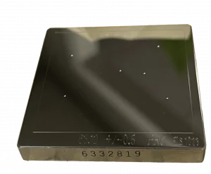 Vickers and Knoop Hardness TestersHardness Test Blocks, Indenters and AccessoriesHardness test blocks, indenters, and accessories support daily verification and reliable operation of metal hardness testing systems. The range includes certified...View product