Impact testing exists because many real-world failures happen under short-duration, high-rate loading such as drops, strikes, tool impacts, and brittle-fracture triggers. Charpy and Izod pendulum tests and drop-tower (drop-weight) tests are two of the most common lab ways to reproduce an impact event, but they answer different engineering questions and produce different kinds of data.
In standards language, notched-bar pendulum impact testing is a single-blow event that creates a complex, multiaxial stress state at a notch under high loading rates. Used appropriately and correlated with service experience for specific materials and temperatures, it can help assess susceptibility to brittle fracture behavior.
So the practical question is not which machine is better, but what decision you are trying to make:
- If you need a standardized, widely comparable toughness indicator for material screening, QA/QC trending, or acceptance decisions, a pendulum test is often the most direct route.
- If you need to understand how a plate, panel, or part behaves in a drop-like event, and especially if the impact curve (not just a single number) matters, a drop tower is usually the better fit. ISO 6603-2 is written specifically for instrumented puncture testing where a force–deflection or force–time diagram at nominally constant striker velocity is required for detailed characterization.
In the sections that follow, we will break down how each method works, what it measures, where it is most useful, and how to choose the right approach without overinterpreting a single impact value.
How Pendulum and Drop Tower Impact Tests Work
Both methods create a controlled “single event” load, but they do it in different ways. A pendulum system delivers impact through a swinging hammer that fractures a standardized specimen and reports the energy absorbed during that break. A drop tower drives a striker into a specimen using a guided falling mass, and depending on the method it can report either a pass/fail threshold or a full impact response curve captured by sensors.
Pendulum Impact Testing in Brief
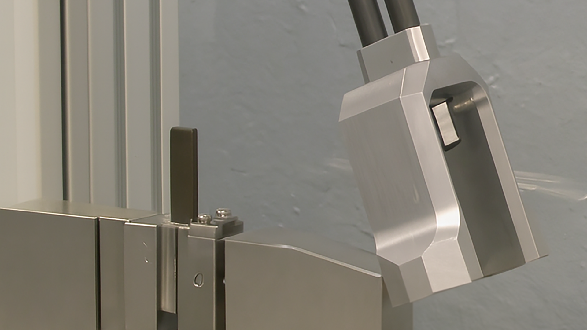
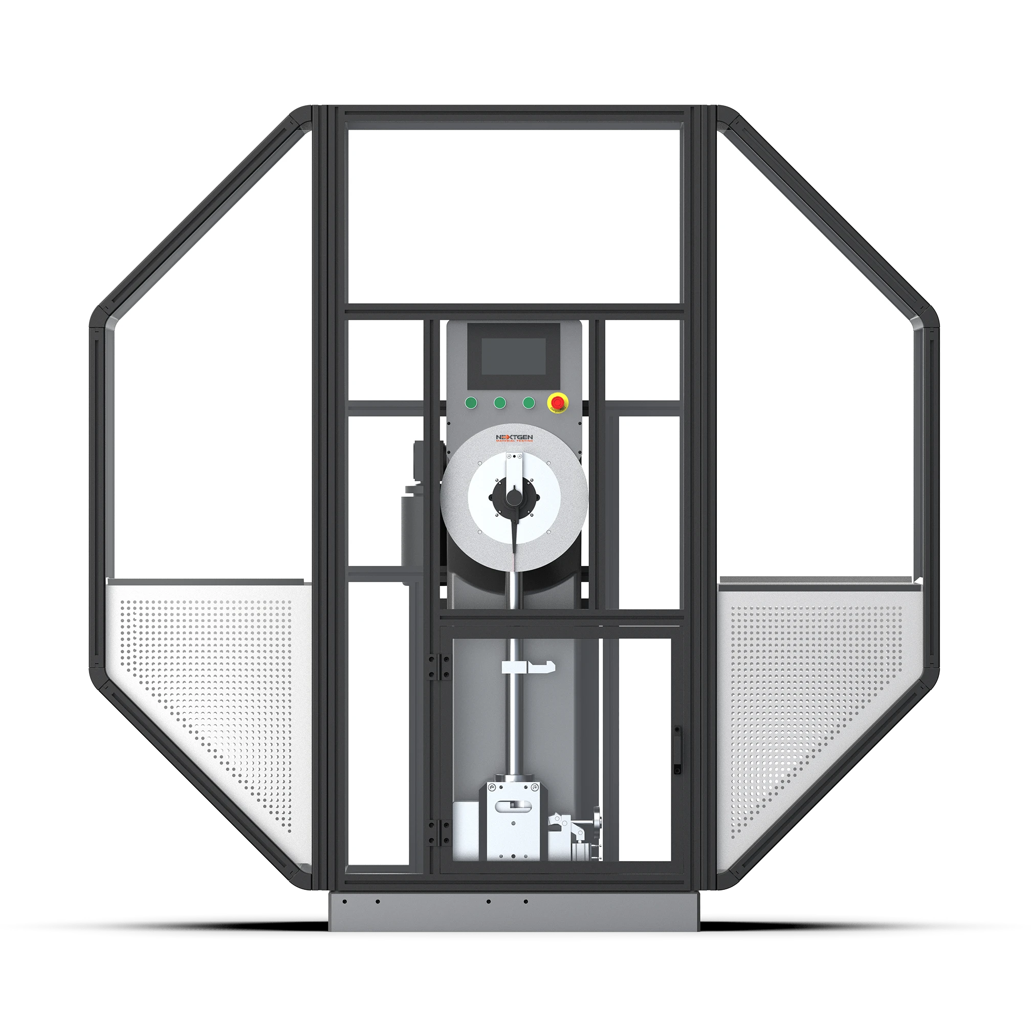 At the machine level, a pendulum impact tester is a rigid frame with a swinging hammer that strikes a specimen supported in a prescribed configuration. ASTM E23 describes the essential ingredients of notched-bar impact testing as a suitable specimen, supports or anvils, a moving mass with enough energy to break the specimen, and a method for measuring the energy absorbed by the broken specimen.
One important detail that helps prevent misunderstandings later is that pendulum tests do not apply a constant velocity throughout fracture. ASTM E23 notes that in a pendulum-type test, the velocity decreases as fracture progresses. It also cautions that when specimen absorbed energies approach a large fraction of the pendulum’s capacity, the pendulum can slow dramatically during fracture, and accurate energies may no longer be obtained.
This is the technical reason standard practice avoids running too close to the machine’s maximum capacity.
For a concrete speed anchor, ASTM E23 requires the pendulum’s tangential impact velocity at the center of strike to be between 3 and 6 m/s.
That gives readers a useful sense of scale: the event is fast, but still controlled and repeatable.
Drop Tower Impact Testing in Brief
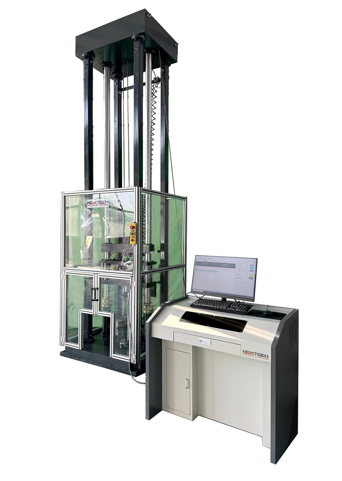 A drop-tower (drop-weight) impact test uses a falling mass (or another energy carrier in some systems) to drive a striker into the specimen. The striker is typically guided so the impact location and alignment are repeatable, and modern systems commonly use guided rails or tower structures for that reason.
ISO 6603-2 describes an instrumented puncture method in which the specimen is punctured at its center with a lubricated striker at nominally uniform velocity while recording the resulting force–deflection or force–time diagram electronically. It also states that the specimen should preferably be clamped during the test.
Unlike a pendulum test, where speed naturally decays during fracture, ISO 6603-2 places explicit constraints on impact velocity to keep results comparable. It specifies a preferred impact velocity of 4.4 ± 0.2 m/s and states that the velocity decrease during the test must not exceed 20%, because viscoelastic materials can show different behavior when the event slows too much. It also notes that for brittle materials a lower impact velocity (1 m/s) can be more appropriate to reduce vibration or noise and improve the quality of the force–deflection diagram.
So while drop-tower testing is often chosen for more application-shaped impacts, it can still be highly standardized when you follow the governing method and its velocity and fixture requirements.
What Each Method Measures
Each impact method has a “headline result,” but the meaning of that result depends on what the test was designed to capture. Pendulum tests are built around a standardized notched-bar fracture event and typically report absorbed energy under defined geometry and conditions. Drop tower methods span everything from pass/fail thresholds to instrumented response curves, which means they can describe not only whether a specimen failed, but how it carried load and absorbed energy during the impact.
Typical Pendulum Results
The primary output of Charpy and Izod style pendulum tests is the energy absorbed in breaking a specimen under defined geometry and test conditions. For metals, ISO 148-1 defines the Charpy pendulum impact method as a test for determining the energy absorbed in an impact test, and ASTM E23 similarly centers absorbed energy as the main reported value.
ASTM E23 also includes additional reporting options such as lateral expansion and fracture appearance (for example, percent shear) when more detail is needed than basic commercial acceptance reporting.
For plastics, ASTM D256 states that the Izod pendulum impact test indicates the energy to break standard test specimens of specified size under stipulated parameters of specimen mounting, notching, and velocity at impact.
In practice, results are commonly reported as impact energy and a derived impact strength term (energy normalized by thickness), typically averaged over multiple specimens. Intertek’s summary of notched Izod testing reflects this common reporting approach and gives typical specimen dimensions used in the method.
A useful nuance for keeping the blog technically honest is that the “energy lost” by the pendulum during breakage is not a pure material toughness value. ASTM D256 explicitly lists multiple contributors, including fracture initiation, fracture propagation, toss correction (throwing broken pieces), bending of the specimen, vibrations in the pendulum and frame, friction and windage, and local indentation or plastic deformation at impact.
That is a standards-backed reason to caution readers against comparing results across different fixture styles, striker geometries, or machines that are not maintained and verified consistently.
It is also worth stating a limitation that many readers miss. ASTM D6110 (Charpy for plastics) warns that even large differences observed under one set of test conditions do not guarantee the same relationship under another set of conditions.
This supports a practical reminder to report the exact method, specimen type, notch, conditioning, and test temperature whenever impact values are shared.
Typical Drop Tower Results
Drop tower testing can range from simple pass/fail outcomes to fully instrumented measurements, depending on the standard and the configuration.
For a standards-based definition of what instrumented drop testing is intended to measure, ASTM D3763 is explicit: it is designed to provide load versus deformation response of plastics under essentially multiaxial deformation conditions at impact velocities, and it provides a measure of the material’s rate sensitivity to impact.
ISO 6603-2 similarly defines the instrumented puncture test around recording a force–deflection or force–time diagram at nominally constant striker velocity for detailed characterization of impact behavior.
Instrumented vs Non-Instrumented Drop Tests
ISO 6603-2 provides a clean way to explain “instrumented” without turning it into a buzzword. The method uses instruments to measure force and deflection, and energy is defined based on the force–deflection response up to a specified deflection.
ISO 6603-2 also includes interpretation cues via example force–deflection diagrams, and it notes how features such as yielding and post-crack vibration artifacts can appear in the recorded signal, which is helpful context for engineers reading curves.
In practical reporting, engineers often extract curve features such as peak load, deflection at peak load, energy at peak load, total absorbed energy, and failure type. This aligns with how labs and test summaries commonly describe ASTM D3763 style results.
Specimens, Fixtures, and Test Realism
The biggest practical difference between these methods is what they are designed to test.
Pendulum impact is usually a coupon-style test built around standardized notched bars. That makes it strong for repeatable material comparisons.
Drop tower methods often use plates, panels, or part-level fixtures to recreate a more application-shaped impact event. Both can be controlled and repeatable, but specimen geometry and fixturing directly affect how transferable the results are.
Standard Notched Bars for Pendulum Tests
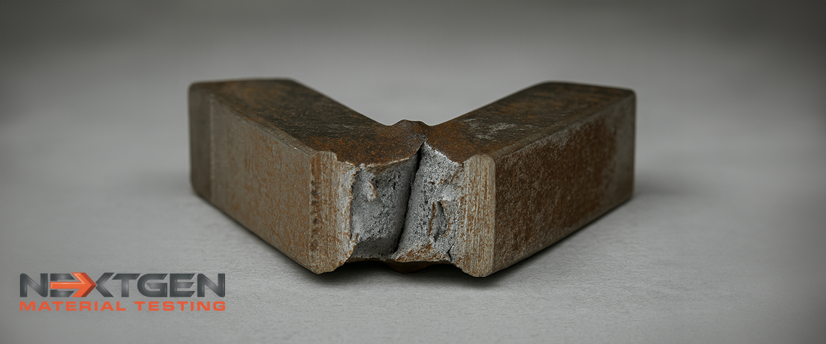
Pendulum impact testing typically uses standardized notched bars because the notch concentrates stress and makes the test sensitive to brittle fracture behavior.
ASTM E23 includes the canonical Charpy V-notch and U-notch specimen geometries and tolerances for metals, including the common 10 × 10 × 55 mm bar format with tightly controlled notch dimensions.
A practical takeaway from ASTM E23 is that notch quality matters a lot. The standard emphasizes that variations in notch dimensions seriously affect results.
Common sources of avoidable variability include:
- notch machining quality and tool wear
- verification of notch geometry and specimen dimensions
- differences in support condition and striker setup
For plastics, consistent geometry is also central.
Intertek’s overview of notched Izod testing under ASTM D256 describes an 80 × 10 × 4 mm specimen and ties reported impact energy and impact strength to that standardized geometry and method.
ISO 180 also specifies Izod impact strength determination for plastics under defined conditions and allows multiple specimen/configuration variants depending on material and notch type. That is a good reason to always cite the exact method and configuration in reports.
One more point that prevents confusion: Charpy and Izod are not the same setup.
ASTM E23 describes Charpy as a “simple-beam” arrangement and Izod as a “cantilever-beam” arrangement, which changes how the specimen is loaded during impact.
Plates, Panels, and Parts for Drop Tower Tests
Drop tower tests often use flat plates or panels, puncture fixtures, or part-level setups to better match real impact scenarios.
ISO 6603-2 is explicitly written for rigid plastics in the form of flat specimens punctured at the center by a lubricated striker, with the specimen preferably clamped.
It also defines an applicability window in thickness (1 mm to 4 mm). That is a useful “realism within limits” reminder: realistic standards usually define where the method is valid.
For composites, ASTM D7136 is a clear example of why drop towers exist in engineering development. It determines damage resistance of multidirectional polymer-matrix composite laminated plates subjected to a drop-weight impact event.
Drop testing can also be used as a comparative ranking tool, not only as field simulation.
ASTM D5420 (Gardner impact) covers relative ranking of materials according to the energy required to crack or break flat, rigid plastic specimens under specified falling-weight striker impact conditions.
A credibility point worth stating explicitly is a limitation from ISO 6603-2: the impact behavior of finished products cannot be predicted directly from this test. Specimens may be taken from finished products, but direct prediction is not guaranteed.
Energy and Impact Speed
Impact testing is fast, but it is not arbitrary. Each method operates within typical speed windows and energy envelopes, and those ranges shape what the results mean in practice.
Pendulum Energy and Speed Context
For pendulum testing on metals, standards constrain impact speed rather than treating it as a free variable. A useful benchmark is the tangential impact velocity at the strike point, which is specified to fall within a defined range for Charpy style metal testing.
In everyday lab terms, many metal-capable pendulum systems operate near the middle of that range. That helps readers visualize pendulum impact as a repeatable, controlled strike rather than a slow bend test.
Energy capacity is where pendulum systems tend to split into two practical classes:
- Plastics and composites class pendulums typically cover lower energy ranges, suitable for Charpy, Izod, and related plastic impact methods.
- Metals class pendulums commonly reach much higher energies, sized to fracture metallic specimens reliably under standard conditions.
One operational limit worth stating is that good practice avoids running too close to the upper measurement limit of the machine. When absorbed energies approach a large fraction of the pendulum’s capacity, the system can slow substantially during fracture and measurement accuracy can degrade. The practical takeaway is simple: capacity selection should leave headroom above the expected absorbed energy range.
Drop Tower Energy and Speed Context
Drop towers cover a broader energy range because the event is configurable. You can change mass, drop height, striker geometry, and fixtures to match applications that range from thin rigid sheets to thicker plates and composite laminates.
A key point for readers is that “drop testing” can still be highly standardized. In instrumented puncture testing of rigid plastics, the method can specify a preferred impact velocity and even limit how much the striker is allowed to slow during the event, because viscoelastic materials can produce non-comparable results if the impact speed decays too much.
It is also worth noting that standards sometimes recommend lower impact velocities for brittle materials to reduce vibration and noise and improve the quality of the recorded curve. This reinforces an important idea: drop tower testing is not simply “pick a height and see what happens.” In many standardized methods, speed control and fixture requirements are part of what makes results comparable across labs.
Standards and Common Use Cases
 Rather than presenting standards as a list of codes, it’s more useful to map each standard to the specimen type and the engineering decision it informs. This keeps test selection tied to the outcome you need, not just the method number.
Pendulum Standards for Plastics and Metals
For metals, Charpy and Izod notched-bar standards are most often used when the decision is material qualification, comparison, or acceptance style testing under defined conditions. These methods are designed around standardized notched bars and absorbed energy reporting, with options to report additional fracture indicators depending on the standard and reporting needs.
For plastics, pendulum Charpy and pendulum Izod standards similarly support comparative ranking and QC trending within clearly defined specimen geometries and test conditions. A practical nuance for this section is that plastics standards often allow multiple specimen and configuration variants depending on material and notch type, so it is important to cite the exact method and configuration whenever values are reported.
Drop Tower Standards for Plastics and Composites
For rigid plastics, instrumented puncture standards focus on measuring force and deflection during the impact and recording the response as a curve. These methods are used when you need more than pass/fail and want detailed characterization of how the specimen carries load and absorbs energy during the event.
For falling-weight impacts on rigid plastic plates, there are also standards designed specifically for relative ranking. In other words, drop testing is not always “simulate the field.” In many cases it is a controlled comparative tool for material selection and specification work.
For composites, drop-weight impact standards are widely used to evaluate damage resistance of laminated plates under a controlled impact event. This supports engineering decisions where the key concern is impact damage and its consequences, not just a single absorbed-energy number.
If you decide later to add a short metals sidebar, drop-weight methods also exist for specific steel and pipeline-relevant fracture transition and tear behavior use cases, but that sits slightly outside the core pendulum-versus-drop-tower comparison for plastics and general product impacts.
Common Pitfalls and How to Avoid Them
Impact data is easy to misuse if you treat it like a universal design property. The best way to keep results meaningful is to control the test setup tightly and be honest about what the method can and cannot predict.
Here are the issues we see most often, and the practical fixes.
Overinterpreting a Single Impact Number
A pendulum result or a single pass/fail threshold is not automatically transferable to a different specimen geometry, notch, temperature, or impact rate.
How to avoid it:
- Always report the exact standard, specimen type, notch type, and conditioning temperature used.
- Treat results as a comparison within the same method and configuration, not a universal material constant.
Comparing Non-Comparable Setups
Two labs can both say “Charpy” or “drop test,” but use different striker geometries, supports, specimen sizes, or fixtures. Those differences can shift results enough to invalidate comparisons.
How to avoid it:
- Keep fixture style, striker geometry, and specimen geometry consistent across a dataset.
- When results come from different labs, confirm the configuration details match before comparing.
Notch Quality and Dimensional Control in Pendulum Testing
Notched-bar impact methods are intentionally notch-sensitive. Small differences in notch geometry, radius, or machining quality can create large differences in absorbed energy.
How to avoid it:
- Treat notch machining and verification as part of the measurement system, not sample prep overhead.
- Use consistent specimen prep equipment and verify notch geometry routinely, especially when tracking trends over time.
Running Too Close to Pendulum Capacity
Pendulum systems can lose accuracy when the specimen absorbs a large fraction of the machine’s capacity. As the fracture progresses, the pendulum slows, and extreme slow-down can distort the energy reading.
How to avoid it:
- Choose a pendulum capacity that leaves headroom above the expected absorbed-energy range.
- If results are clustering near the upper end, move to a higher-energy configuration or adjust the method appropriately.
Remembering That Absorbed Energy Includes Other Losses
Pendulum energy readings reflect the total energy loss during the event. That can include effects that are not purely fracture toughness, such as vibration, friction, specimen bending, or how broken pieces are ejected.
How to avoid it:
- Keep method details consistent and maintain the machine.
- Avoid mixing data from different striker shapes, supports, or poorly verified setups.
Controlling Velocity and Signal Quality in Instrumented Drop Tests
Instrumented drop tests are only as good as the velocity control and the quality of the measured signal. Excessive velocity decay, vibration artifacts after unstable cracking, or noisy force signals can make curves hard to interpret.
How to avoid it:
- Verify impact velocity at the event, not only the drop height.
- Use proper filtering and sensor setup, and watch for ringing or vibration artifacts in the curve.
- For very brittle materials, consider lower impact velocity when the method allows it to improve curve quality.
Avoiding Misreads of Pass/Fail Results
Pass/fail tests are useful, but they do not explain how close the specimen was to failure or how damage initiated and progressed.
How to avoid it:
- When decisions depend on damage progression, use instrumented testing or add intermediate metrics.
- Pair pass/fail thresholds with visual inspection criteria when damage morphology matters.
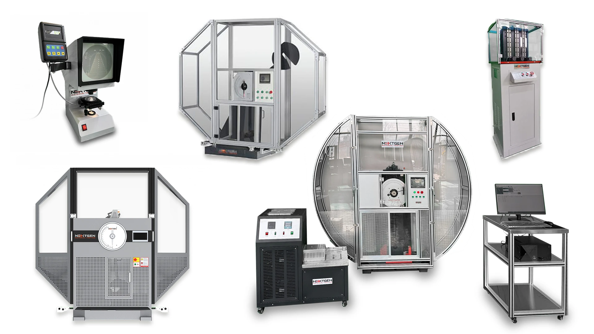
NextGen Material Testing Capabilities
If you are building or expanding impact-testing capability, we support both of the common workflows discussed in this blog: standardized pendulum impact testing and controlled drop-weight impact testing. We also cover the steps that often determine data quality, such as specimen preparation, notch verification, and temperature conditioning.
Pendulum Impact Testing Systems
Our pendulum lineup supports both lower-energy and higher-energy needs.
It includes a Class J automatic Charpy and Izod impact system designed for softer metals, plastics, and rubber, with a Charpy test range from 1 J to 50 J and an Izod range from 1 J to 22 J. The system can also be equipped with a tensile impact pendulum and fixtures for film and sheet testing.
For higher rigidity and common metal-testing ranges, our single-column Charpy and Charpy/Izod systems span roughly 150 J up to 750 J.
We also offer a dual-column servo-motor Charpy system with selectable capacities including 300 J, 450 J, 600 J, and up to 750 J for Charpy and Izod methods.
Specimen Preparation and Verification
Because notch geometry and consistency strongly influence pendulum impact results, we include tooling typically used to keep specimen prep consistent:
- specimen notching and broaching equipment
- notch verification projector system
Temperature Conditioning for Impact Specimens
For low-temperature Charpy programs, we offer impact specimen cooling chambers with models supporting setpoints down to -60°C, -80°C, -100°C, or -196°C depending on the configuration, with tight temperature control for consistent conditioning.
Drop-Weight Impact Testing
Alongside pendulum systems, we also offer computer-controlled drop-weight impact testing equipment for applications where a falling-weight event or drop-style configuration is required.
Practical Takeaways and Next Steps
Pendulum impact testing and drop tower impact testing are both valuable, but they are built for different decisions. Pendulum methods are standardized notched-bar tests that primarily deliver absorbed energy (and, in some cases, additional fracture descriptors), which makes them well suited to material screening, QA/QC trending, supplier comparison, and acceptance work under tightly defined specimen geometries and test conditions.
Drop towers create controlled falling-weight impact events that can be shaped around plates, panels, laminates, or components. In instrumented form, they can provide force–deflection or force–time data and derived energy measures that support deeper characterization of impact response and damage progression. At the same time, both approaches come with known limitations, so the most reliable comparisons are made within the same standard, configuration, and conditioning window.
If you are upgrading a lab, expanding test capability, or trying to match a method to a specific standard or application, we can help you define the right workflow and equipment configuration. Contact us to discuss your requirements or request a quote for impact testing equipment, and we will help you map your material, specimen geometry, and reporting needs to an appropriate pendulum or drop-weight setup.